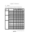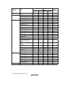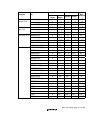
Rev. 5.00, 09/03, page 718 of 760
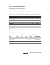
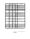
Reset Power-Down
Category Pin
Power-On
Reset
Manual
Reset
Standby Sleep
Bus
Released
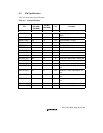
AN[5:0]/PTL[5:0] Z ZI
*
6
ZIIAnalog
AN[6:7]/DA[1:0]/PTL[6:7] Z ZI
*
6
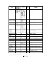
OZ
*
11
IO
*
8
IO
*
8
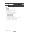
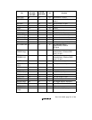
I: Input
O: Output
H: High-level output
L: Low-level output
Z: High impedance
P: Input or output depending on register setting
K: Input pin is high impedance, output pin holds its state
V: I/O buffer off, pull-up MOS on
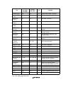
Notes: 1. Depending on the clock mode (MD2–MD0 setting).
2. K or P when the port function is used.
3. K or P when the port function is used. Z or O when the port function is not used
depending on register setting.
4. K or P when the port function is used. I or O when the port function is not used
depending on register setting.
5. Depending on register setting.
6. I or O when the port function is used.
7. Input Schmitt buffers of IRQ[5.0] and ADTRG on; other input buffers off.
8. O when DA output is enabled; otherwise I depending on register setting.
9. In standby mode, Z or L depending on register setting.
10.In standby mode, Z or H depending on register setting.
11.O when DA output is enabled; Z otherwise.


