Rev. 5.00, 09/03, page 393 of 760
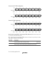
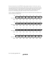
Bits 7 to 3—Reserved: These bits are always read as 0. The write value should always be 0.
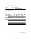
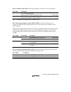
Bit 2—Counter Start 2 (STR2): Selects whether to run or halt timer counter 2 (TCNT2).
Bit 2: STR2 Description
0 TCNT2 count halted (Initial value)
1 TCNT2 counts
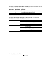
Bit 1—Counter Start 1 (STR1): Selects whether to run or halt timer counter 1 (TCNT1).
Bit 1: STR1 Description
0 TCNT1 count halted (Initial value)
1 TCNT1 counts
Bit 0—Counter Start 0 (STR0): Selects whether to run or halt timer counter 0 (TCNT0).
Bit 0: STR0 Description
0 TCNT0 count halted (Initial value)
1 TCNT0 counts
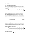
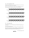
12.2.3 Timer Control Registers (TCR)
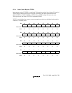
The timer control registers (TCR) control the timer counters (TCNT) and interrupts. The TMU has
three TCR registers, one for each channel.
The TCR registers are 16-bit readable/writable registers that control the issuance of interrupts
when the flag indicating timer counter (TCNT) underflow has been set to 1, and also carry out
counter clock selection. When the external clock has been selected, they also select its edge.
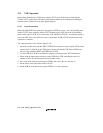
Additionally, TCR2 controls the channel 2 input capture function and the issuance of interrupts
during input capture. The TCR registers are initialized to H'0000 by a power-on reset and manual
reset, but are not initialized in standby mode and retain their contents.


