Rev. 5.00, 09/03, page 396 of 760
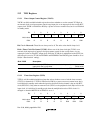
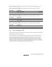
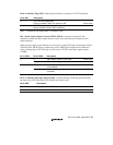
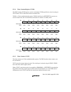
Bits 4 and 3—Clock Edge 1 and 0 (CKEG1, CKEG0): Select the external clock edge when the
external clock is selected, or when the input capture function is used.
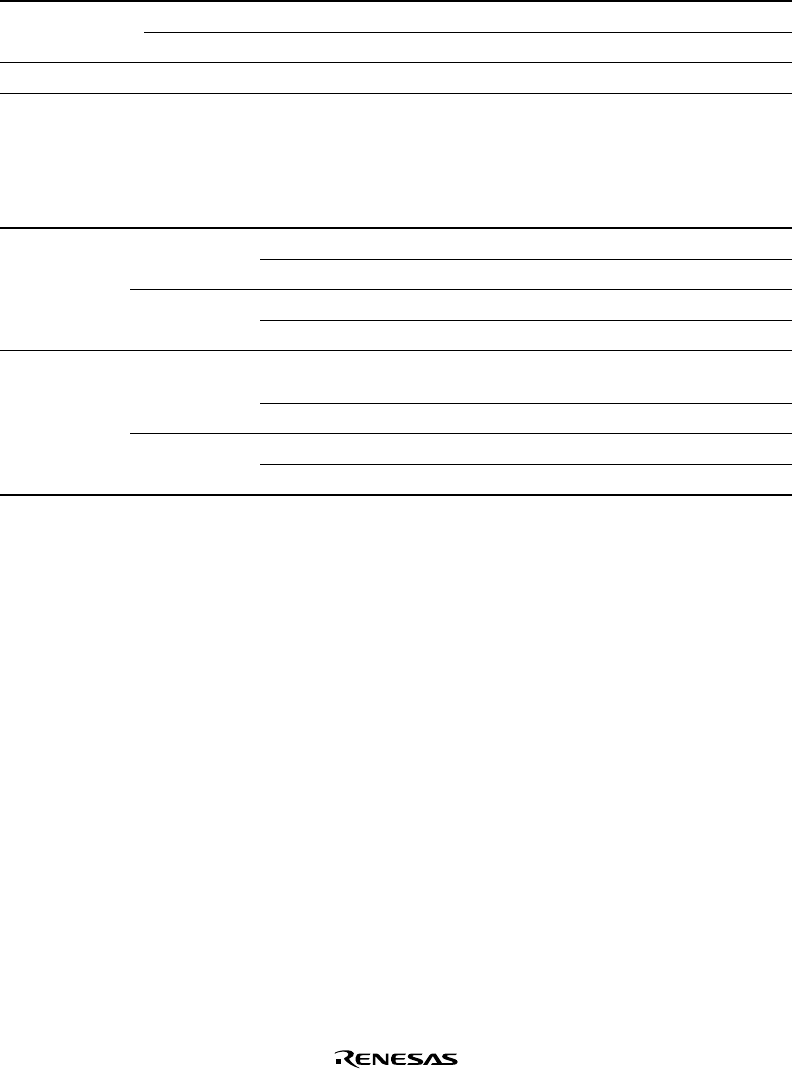
Bit 4: CKEG1 Bit 3: CKEG0 Description
0 0 Count/capture register set on rising edge (Initial value)
1 Count/capture register set on falling edge
1 X Count/capture register set on both rising and falling edge
Note: X means 0, 1, or ‘Don’t care’.
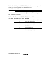
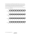
Bits 2 to 0—Timer Prescaler 2 to 0 (TPSC2 to TPSC0): Select the TCNT count clock.
Bit 2: TPSC2 Bit 1: TPSC1 Bit 0: TPSC0 Description
0 0 0 Internal clock: count on Pφ/4 (Initial value)
1 Internal clock: count on Pφ/16
1 0 Internal clock: count on Pφ/64
1 Internal clock: count on Pφ/256
1 0 0 Internal clock: count on clock output of on-chip
RTC (RTC CLK)
1 Count on TCLK pin input
1 0 Reserved (Setting prohibited)
1 Reserved (Setting prohibited)


