Rev. 5.00, 09/03, page 62 of 760
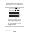
5. The MMU control register (MMUCR) residing at address H'FFFFFFE0, which makes the
MMU settings described in figure 3.3. Any program that modifies MMUCR should reside in
the P1 or P2 area.
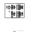
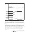
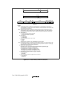
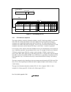
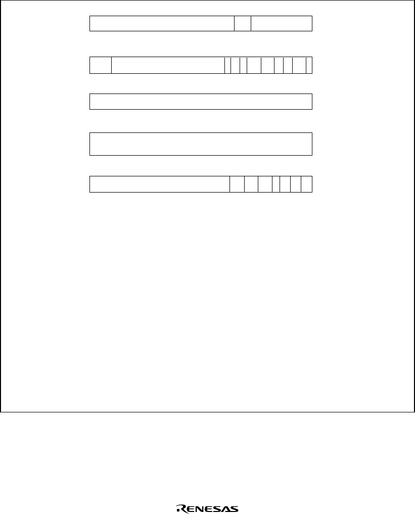
The MMU registers are shown in figure 3.3.
31 7
VPN
PTEH
PTEL
ASID0
PPN000
010
31 29 28
31
TTB
TTB
0
31
Virtual address causing TLB-related
or address error exception
TEA
0
MMUCR
0
31 8 46573210
SV RC00 0 TF IX AT
0: Reserved bits. Always read as 0. Writing is ignored. However, 0 should also be
specified in a write to MMUCR only.
SV: Single virtual memory mode bit. 0: Multiple virtual memory mode
1: Single virtual memory mode
RC: A 2-bit random counter, automatically updated by hardware according to the
following rules in the event of an MMU exception. When a TLB miss exception
occurs, all TLB entry ways corresponding to the virtual address at which the
exception occurred are checked, and if all ways are valid, 1 is added to RC; if
there is one or more invalid way, they are set by priority from way 0, in the order:
way 0, way 1, way 2, way 3. In the event of an MMU exception other than a TLB
miss exception, the way which caused the exception is set in RC.
TF: TLB flush bit. Write 1 to flush the TLB (clear all valid bits of the TLB to 0). Always
reads 0.
IX: Index mode bit. When 0, VPN bits 16−12 are used as the TLB index number.
When 1, the value obtained by EX-ORing ASID bits 4−0 in PTEH and VPN bits
16−12 are used as the TLB index number.
AT: Address translation bit. Enables/disables the MMU.
0: MMU disabled
1: MMU enabled
Note: * Refer to section 3.3, TLB Functions.
64321010
PR
*
SZ
*
C
*
D
*
89
7
V
*
00 SH
*
0
Figure 3.3 MMU Register Contents


