Rev. 5.00, 09/03, page 581 of 760
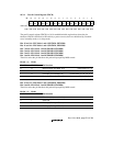
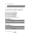
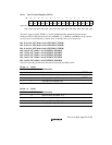
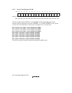
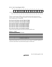
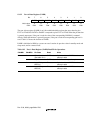
18.3.11 Port L Control Register (PLCR)
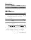
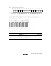
Bit: 15 14 13 12 11 10 9 8 7 6 5 4 3 2 1 0
PL7
MD1
PL7
MD0
PL6
MD1
PL6
MD0
PL5
MD1
PL5
MD0
PL4
MD1
PL4
MD0
PL3
MD1
PL3
MD0
PL2
MD1
PL2
MD0
PL1
MD1
PL1
MD0
PL0
MD1
PL0
MD0
Initial value:0000000000000000
R/W: R/W R/W R/W R/W R/W R/W R/W R/W R/W R/W R/W R/W R/W R/W R/W R/W
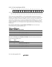
The port L control register (PLCR) is a 16-bit readable/writable register that selects the pin
functions. PLCR is initialized to H'0000 by a power-on reset, but is not initialized by a manual
reset, in standby mode, or in sleep mode.
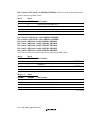
Bits 15 and 14—PL7 Mode 1 and 0 (PL7MD1, PL7MD0)
Bits 13 and 12—PL6 Mode 1 and 0 (PL6MD1, PL6MD0)
Bits 11 and 10—PL5 Mode 1 and 0 (PL5MD1, PL5MD0)
Bits 9 and 8—PL4 Mode 1 and 0 (PL4MD1, PL4MD0)
Bits 7 and 6—PL3 Mode 1 and 0 (PL3MD1, PL3MD0)
Bits 5 and 4—PL2 Mode 1 and 0 (PL2MD1, PL2MD0)
Bits 3 and 2—PL1 Mode 1 and 0 (PL1MD1, PL1MD0)
Bits 1 and 0—PL0 Mode 1 and 0 (PL0MD1, PL0MD0)
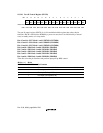
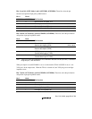
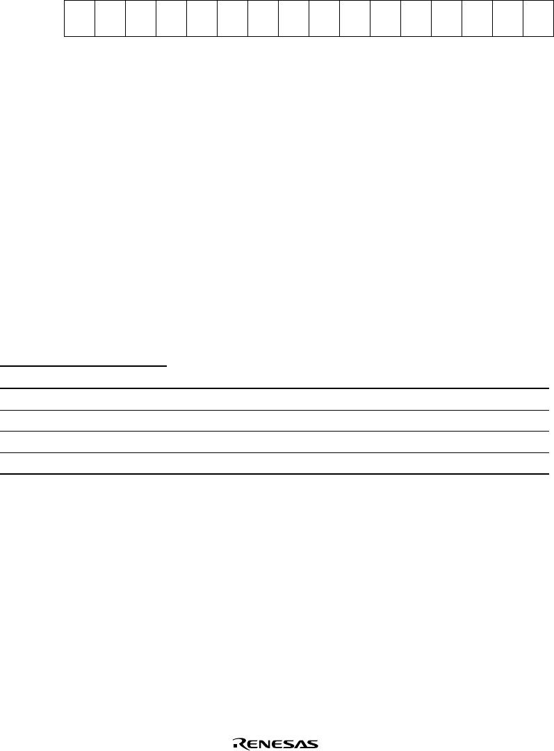
These bits select the pin functions and perform input pull-up MOS control.
Bit (2n + 1) Bit 2n
PLnMD1 PLnMD0 Pin Function
0 0 Other function (see table 18.1) (Initial value)
0 1 Reserved
1 0 Port input (Pull-up MOS: on)
1 1 Port input (Pull-up MOS: off)
(n = 0 to 7)
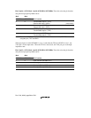
When the DA0 and DA1 pins are used as the D/A converter outputs or when PTL7 and PTL6 are
used in the “other function” state, PLCR should by kept at its initial value.


