Rev. 5.00, 09/03, page 377 of 760
Register Configuration
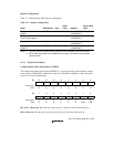
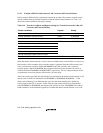
Table 11.7 summarizes the CMT register configuration.
Table 11.7 Register Configuration
Name Abbreviation R/W
Initial
Value Address
Access Size
(Bits)
Compare match timer start
register
CMSTR R/(W) H'0000 H'04000070
(H'A4000070)
*
2
8, 16, 32
Compare match timer
control/status register 0
CMCSR0 R/(W)
*
1
H'0000 H'04000072
(H'A4000072)
*
2
8, 16, 32
Compare match counter 0 CMCNT0 R/W H'0000 H'04000074
(H'A4000074)
*
2
8, 16, 32
Compare match constant
register 0
CMCOR0 R/W H'FFFF H'04000076
(H'A4000076)
*
2
8, 16, 32
Notes: 1. The only value that can be written to the CMF bit in CMCSR0 is 0 to clear the flag.
2. When address translation by the MMU does not apply, the address in parentheses
should be used.
11.4.2 Register Descriptions
Compare Match Timer Start Register (CMSTR)
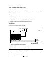
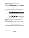
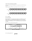
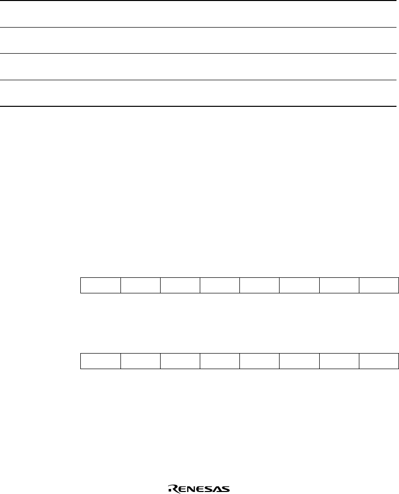
The compare match timer start register (CMSTR) is a 16-bit register that selects whether compare
match counter 0 (CMCNT0) is operated or halted. It is initialized to H'0000 by a reset, but retains
its previous value in standby mode.
Bit: 15 14 13 12 11 10 9 8
————————
Initial value:00000000
R/W:RRRRRRRR
Bit:76543210
———————STR0
Initial value:00000000
R/W:RRRRRRR/WR/W
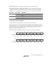
Bits 15 to 2—Reserved: These bits are always read as 0. The write value should alway be 0.
Bit 1—Reserved: This bit can be read or written. The write value should always be 0.


