Rev. 5.00, 09/03, page 225 of 760
10.1.2 Block Diagram
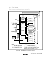
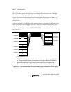
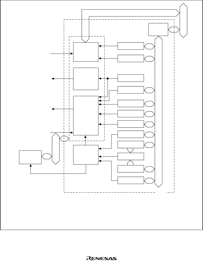
Figure 10.1 shows a block diagram of the bus state controller.
WCR1
WCR2
BCR1
Module bus
MCR
BSC
RFCR
RTCNT
Comparator
Refresh
controller
Peripheral bus
Internal bus
Interrupt
controller
Memory
controller
Area
controller
Wait
controller
WAIT
CS0, CS6 to CS2,
CE2A, CE2B
MCS0 to MCS7
BS
RD
RD/WR
WE3 to WE0
RASxx
CASx
CKE
ICIORD, ICIOWR
IOIS16
WCR:
BCR:
MCR:
PCR:
Legend
Bus
interface
RTCSR
RTCOR
BCR2
PCR
MCSCRn
Wait state control register
Bus control register
Memory control register
PCMCIA control register
RFCR:
RTCNT:
RTCOR:
RTCSR:
MCSCRn:
Refresh count register
Refresh timer count register
Refresh time constant register
Refresh timer control/status register
MCSn control register (n = 0−7)
Figure 10.1 Block Diagram of Bus State Controller


