Rev. 5.00, 09/03, page 361 of 760
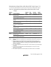
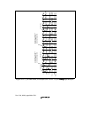
Relationship between Request Modes and Bus Modes by DMA Transfer Category: Table
11.6 shows the relationship between request modes and bus modes by DMA transfer category.
Table 11.6 Relationship between Request Modes and Bus Modes by DMA Transfer
Category
Address
Mode Transfer Category
Request
Mode
Bus
Mode
Transfer
Size (Bits)
Usable
Channels
Dual External device with DACK and
external memory
External B/C 8/16/32/128 0,1
External device with DACK and
memory-mapped external device
External B/C 8/16/32/128 0, 1
External memory and external
memory
All
*
1
B/C 8/16/32/128 0–3
*
5
External memory and memory-
mapped external device
All
*
1
B/C 8/16/32/128 0–3
*
5
Memory-mapped external device
and memory-mapped external
device
All
*
1
B/C 8/16/32/128 0–3
*
5
External memory and on-chip
peripheral module
All
*
2
B/C
*
3
8/16/32
*
4
0–3
*
5
Memory-mapped external device
and on-chip peripheral module
All
*
2
B/C
*
3
8/16/32
*
4
0–3
*
5
On-chip peripheral module and on-
chip peripheral module
All
*
2
B/C
*
3
8/16/32
*
4
0–3
*
5
Single External device with DACK and
external memory
External B/C 8/16/32/128 0, 1
External device with DACK and
memory-mapped external device
External B/C 8/16/32/128 0, 1
B: Burst, C: Cycle-steal
Notes: 1. External requests, auto requests and on-chip peripheral module (CMT) requests are all
available.
2. External requests, auto requests and on-chip peripheral module requests are all
available. When the IrDA, SCIF, or A/D converter is also the transfer request source,
however, the transfer destination or transfer source must be the IrDA, SCIF, or A/D
converter, respectively.
3. If the transfer request source is the IrDA, SCIF, or A/D converter only cycle-steal mode
is available.
4. The access size permitted when the transfer destination or source is an on-chip
peripheral module register.
5. If the transfer request is an external request, only channels 0 and 1 are available.


