Rev. 5.00, 09/03, page 535 of 760
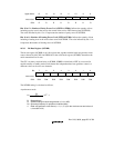
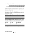
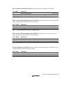
Bit 3—Modem Control Enable (MCE): Enables modem control signals CTS and RTS.
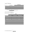
Bit 3: MCE Description
0 Modem signal disabled
*
(Initial value)
1 Modem signal enabled
Note: * CTS is fixed at active 0 regardless of the input value, and RTS is also fixed at 0.
Bit 2—Transmit FIFO Data Register Reset (TFRST): Disables the transmit data in the transmit
FIFO data register and resets the data to the empty state.
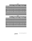
Bit 2: TFRST Description
0 Reset operation disabled
*
(Initial value)
1 Reset operation enabled
Note: * Reset is executed in a reset or in standby mode.
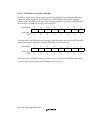
Bit 1—Receive FIFO Data Register Reset (RFRST): Disables the receive data in the receive
FIFO data register and resets the data to the empty state.
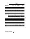
Bit 1: RFRST Description
0 Reset operation disabled
*
(Initial value)
1 Reset operation enabled
Note: * Reset is executed in a reset or in standby mode.
Bit 0—Loop-Back Test (LOOP): Internally connects the transmit output pin (TXD) and receive
input pin (RXD) and enables loop-back testing.
Bit 0: LOOP Description
0 Loop back test disabled (Initial value)
1 Loop back test enabled


