Rev. 5.00, 09/03, page 631 of 760
20.5 Interrupts
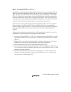
The A/D converter generates an interrupt (ADI) at the end of A/D conversion. The ADI interrupt
request can be enabled or disabled by the ADIE bit in ADCSR.
20.6 Definitions of A/D Conversion Accuracy
The A/D converter compares an analog value input from an analog input channel with its analog
reference value and converts it to 10-bit digital data. The absolute accuracy of this A/D conversion
is the deviation between the input analog value and the output digital value. It includes the
following errors:
• Offset error
• Full-scale error
• Quantization error
• Nonlinearity error
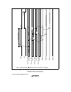
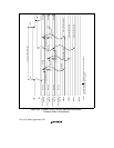
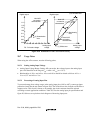
These four error quantities are explained below with reference to figure 20.8. In the figure, the 10
bits of the A/D converter have been simplified to 3 bits.
Offset error is the deviation between actual and ideal A/D conversion characteristics when the
digital output value changes from the minimum (zero voltage) 0000000000 (000 in the figure) to
000000001 (001 in the figure)(figure 20.8, item (1)). Full-scale error is the deviation between
actual and ideal A/D conversion characteristics when the digital output value changes from the
1111111110 (110 in the figure) to the maximum 1111111111 (111 in the figure)(figure 20.8, item
(2)). Quantization error is the intrinsic error of the A/D converter and is expressed as 1/2 LSB
(figure 20.8, item (3)). Nonlinearity error is the deviation between actual and ideal A/D conversion
characteristics between zero voltage and full-scale voltage (figure 20.8, item (4)). Note that it does
not include offset, full-scale, or quantization error.


