Rev. 5.00, 09/03, page 212 of 760
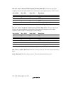
Bits 14, 3, and 2—Internal Clock Frequency Division Ratio (IFC): These bits specify the
frequency division ratio of the internal clock with respect to the output frequency of PLL circuit 1.
Bit 14: IFC2 Bit 3: IFC1 Bit 2: IFC0 Description
000× 1 (Initial value)
001× 1/2
100× 1/3
010× 1/4
Except above value Reserved (Setting prohibited)
Note: Do not set the internal clock frequency lower than the CKIO pin frequency.
Bits 13, 1, and 0—Peripheral Clock Frequency Division Ratio (PFC): These bits specify the
division ratio of the peripheral clock frequency with respect to the frequency of the output
frequency of PLL circuit 1 or the frequency of the CKIO pin.
Bit 13: PFC2 Bit 1: PFC1 Bit 0: PFC0 Description
000× 1
001× 1/2
100× 1/3
010× 1/4 (Initial value)
101× 1/6
Except above value Reserved (Setting prohibited)
Note: Do not set the peripheral clock frequency higher than the CKIO pin frequency.
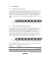
Bits 12 to 9, 7, and 6—Reserved: These bits are always read as 0. The write value should always
be 0.
Bit 8—Reserved: This bit is always read as 1. The write value should always be 1.


