Rev. 5.00, 09/03, page 383 of 760
11.5 Examples of Use
11.5.1 Example of DMA Transfer between On-Chip IrDA and External Memory
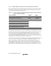
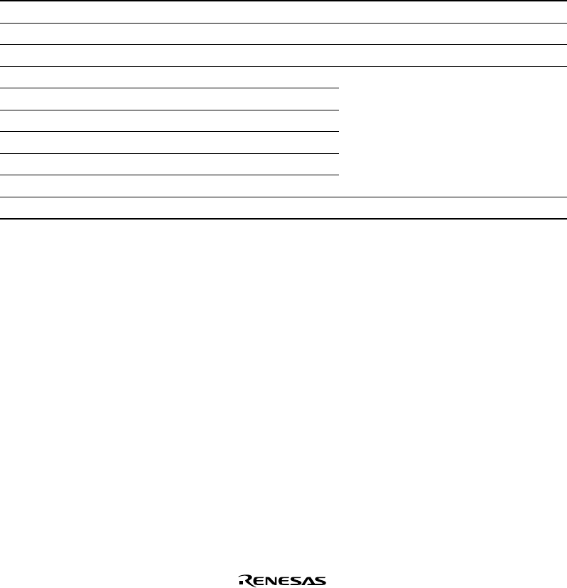
In this example, receive data of the on-chip IrDA is transferred to external memory using DMAC
channel 3. Table 11.8 shows the transfer conditions and register settings. In addition, it is
recommended that the trigger for the number of receive FIFO data bytes in IrDA be set to 1
(RTRG1 = RTRG0 = 0 in SCFCR).
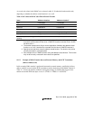
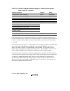
Table 11.8 Transfer Conditions and Register Settings for Transfer between On-Chip SCI
and External Memory
Transfer Conditions Register Setting
Transfer source: RDR1 of on-chip IrDA SAR3 H'0400014A
Transfer destination: External memory DAR3 H'00400000
Number of transfers: 64 DMATCR3 H'00000040
Transfer source address: Fixed CHCR3 H'00004B05
Transfer destination address: Incremented
Transfer request source: IrDA (RXI1)
Bus mode: Cycle-steal
Transfer unit: Byte
Interrupt request generated at end of transfer
Channel priority order: 0 > 2 > 3 > 1 DMAOR H'0101


