Rev. 5.00, 09/03, page 243 of 760
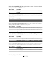
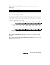
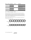
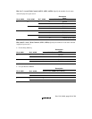
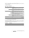
Bits 9 to 7—Area 4 Wait Control (A4W2, A4W1, A4W0): Specify the number of wait states
inserted in physical space area 4.
Description
Bit 9: A4W2 Bit 8: A4W1 Bit 7: A4W0 Inserted Wait State W
WW
WA
AA
AI
II
IT
TT
T Pin
0000 Ignored
1 1 Enabled
1 0 2 Enabled
1 3 Enabled
1004 Enabled
1 6 Enabled
1 0 8 Enabled
1 10 Enabled (Initial value)
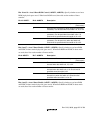
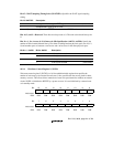
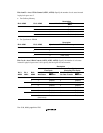
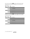
Bits 6 and 5—Area 3 Wait Control (A3W1, A3W0): Specify the number of wait states inserted
in physical space area 3.
• For Ordinary Memory
Description
Bit 6: A3W1 Bit 5: A3W0 Inserted Wait States W
WW
WA
AA
AI
II
IT
TT
T Pin
0 0 0 Ignored
1 1 Enabled
1 0 2 Enabled
1 3 Enabled (Initial value)
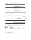
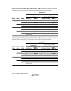
• For Synchronous DRAM
Description
Bit 6: A3W1 Bit 5: A3W0 Synchronous DRAM: CAS Latency
00 1
11
10 2
1 3 (Initial value)


