Rev. 5.00, 09/03, page 149 of 760
Section 7 User Break Controller
7.1 Overview
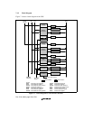
The user break controller (UBC) provides functions that simplify program debugging. This
function makes it easy to design an effective self-monitoring debugger, enabling the chip to debug
programs without using an in-circuit emulator. Break conditions that can be set in the UBC are
instruction fetch or data read/write, data size, data content, address value, and stop timing during
instruction fetches.
7.1.1 Features
The user break controller has the following features:
• The following break comparison conditions can be set.
Number of break channels: two channels (channels A and B)
User break can be requested as either the independent or sequential condition on channels A
and B (sequential break setting: channel A and, then channel B match with logical AND, but
not in the same bus cycle).
Address (Compares 40 bits comprised of a 32-bit logical address prefixed with an ASID
address. Comparison bits are maskable in 32-bit units, user can easily program it to mask
addresses at bottom 12 bits (4-k page), bottom 10 bits (1-k page), or any size of page, etc.
One of two address buses (CPU address bus (LAB), cache address bus (IAB)) can be
selected.
Data (only on channel B, 32-bit maskable)
One of the two data buses (CPU data bus (LDB), cache data bus (IDB)) can be selected.
Bus master: CPU cycle or DMAC cycle
Bus cycle: instruction fetch or data access
Read/write
Operand size: byte, word, or longword
• User break is generated upon satisfying break conditions. A user-designed user-break
condition exception processing routine can be run.
• In an instruction fetch cycle, it can be selected that a break is set before or after an instruction
is executed.
• Maximum repeat times for the break condition: 2
12
– 1 times.
• Eight pairs of branch source/destination buffers.


