Rev. 5.00, 09/03, page xxxix of xliv
Tables
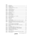
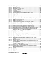
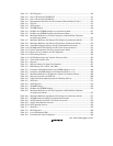
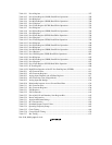
Table 1.1 SH7709S Features .................................................................................................. 2
Table 1.2 Characteristics......................................................................................................... 5
Table 1.3 SH7709S Pin Function ........................................................................................... 9
Table 2.1 Initial Register Values ............................................................................................ 22
Table 2.2 Addressing Modes and Effective Addresses........................................................... 28
Table 2.3 Instruction Formats................................................................................................. 32
Table 2.4 Classification of Instructions .................................................................................. 35
Table 2.5 Instruction Code Format......................................................................................... 38
Table 2.6 Data Transfer Instructions ...................................................................................... 39
Table 2.7 Arithmetic Instructions........................................................................................... 41
Table 2.8 Logic Operation Instructions .................................................................................. 44
Table 2.9 Shift Instructions.....................................................................................................45
Table 2.10 Branch Instructions................................................................................................. 46
Table 2.11 System Control Instructions.................................................................................... 47
Table 2.12 Instruction Code Map ............................................................................................. 50
Table 3.1 Register Configuration............................................................................................ 61
Table 3.2 Access States Designated by D, C, and PR Bits..................................................... 68
Table 4.1 Register Configuration............................................................................................ 85
Table 4.2 Exception Event Vectors ........................................................................................ 87
Table 4.3 Exception Codes..................................................................................................... 90
Table 4.4 Types of Reset ........................................................................................................ 95
Table 5.1 Cache Specifications............................................................................................... 103
Table 5.2 LRU and Way Replacement (When the cache lock function is not used) .............. 105
Table 5.3 Register Configuration............................................................................................ 105
Table 5.4 Way Replacement when PREF Instruction Ended Up in a Cache Miss ................. 107
Table 5.5 Way Replacement when Instructions Except for PREF Instruction Ended Up
in a Cache Miss....................................................................................................... 108
Table 5.6 LRU and Way Replacement (when W2LOCK=1) ................................................. 108
Table 5.7 LRU and Way Replacement (when W3LOCK=1) ................................................. 108
Table 5.8 LRU and Way Replacement (when W2LOCK=1 and W3LOCK=1)..................... 108
Table 6.1 INTC Pins............................................................................................................... 119
Table 6.2 INTC Registers....................................................................................................... 120
Table 6.3 IRL3–IRL0/IRLS3–IRLS0 Pins and Interrupt Levels............................................ 123
Table 6.4 Interrupt Exception Handling Sources and Priority (IRQ Mode) ........................... 126
Table 6.5 Interrupt Exception Handling Sources and Priority (IRL Mode)............................ 128
Table 6.6 Interrupt Levels and INTEVT Codes...................................................................... 130
Table 6.7 Interrupt Request Sources and IPRA–IPRE............................................................ 131
Table 6.8 Interrupt Response Time......................................................................................... 146
Table 7.1 Register Configuration............................................................................................ 151
Table 7.2 Data Access Cycle Addresses and Operand Size Comparison Conditions............. 171
Table 8.1 Power-Down Modes............................................................................................... 182


