Rev. 5.00, 09/03, page 200 of 760
8.7.3 Hardware Standby Mode Timing
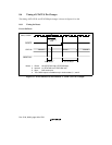
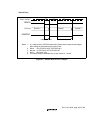
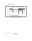
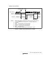
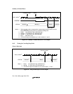
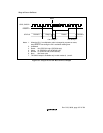
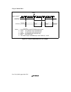
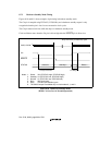
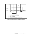
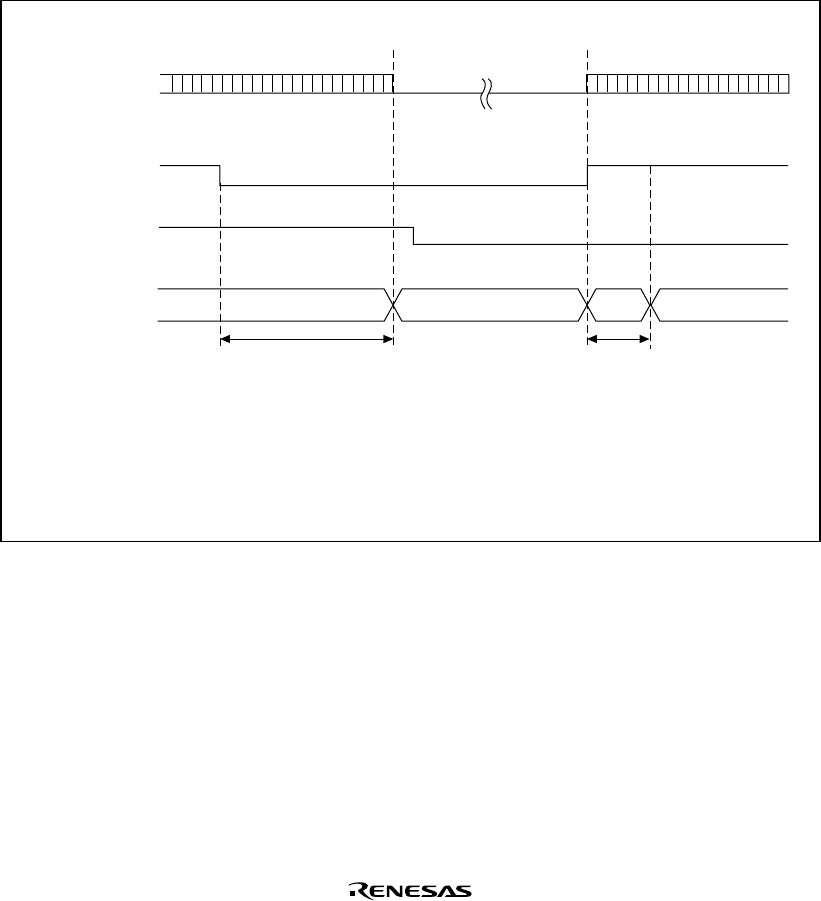
Figures 8.10 and 8.11 show examples of pin timing in hardware standby mode.
The CA pin is sampled using EXTAL2 (32.768 kHz), and a hardware standby request is only
recognized when the pin is low for two consecutive clock cycles.
The CA pin must be held low while the chip is in hardware standby mode.
Clock oscillation starts when the CA pin is driven high after the RESETP pin is driven low.
Normal*
3
STATUS
CA
CKIO, CKIO2*
6
Standby*
2
Reset*
1
R
ESETP
Undefined
Rcyc: EXTAL2 (32.768 kHz) cycle
2 Rcyc or more*
5
0−10Bcyc*
4
Notes: 1. Reset: HH (STATUS1 high, STATUS0 high)
2. Standby: LH (STATUS1 low, STATUS0 high)
3. Normal: LL (STATUS1 low, STATUS0 low)
4. Bcyc: Bus clock cycle
5. Rcyc: EXTAL2 (32.768 kHz) cycle
6. The CKIO2 output is available only in clock modes 0, 1, and 2.
Figure 8.10 Hardware Standby Mode
(When CA Goes Low in Normal Operation)


