Rev. 5.00, 09/03, page 478 of 760
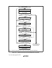
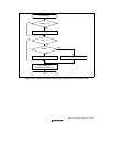
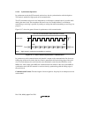
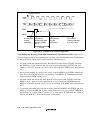
In transmitting serial data, the SCI operates as follows:
1. The SCI monitors the TDRE bit in SCSSR. When TDRE is cleared to 0 the SCI recognizes
that the transmit data register (SCTDR) contains new data and loads this data from SCTDR
into the transmit shift register (SCTSR).
2. After loading the data from SCTDR into SCTSR, the SCI sets the TDRE bit to 1 and starts
transmitting. If the transmit-data-empty interrupt enable bit (TIE) in SCSCR is set to 1, the SCI
requests a transmit-data-empty interrupt (TXI) at this time.
If clock output mode is selected, the SCI outputs eight synchronous clock pulses. If an external
clock source is selected, the SCI outputs data in synchronization with the input clock. Data is
output from the TxD pin in order from the LSB (bit 0) to the MSB (bit 7).
3. The SCI checks the TDRE bit when it outputs the MSB (bit 7). If TDRE is 0, the SCI loads
data from SCTDR into SCTSR, then begins serial transmission of the next frame. If TDRE is
1, the SCI sets the TEND bit in SCSSR to 1, transmits the MSB, then holds the transmit data
pin (TxD) in the MSB state. If the transmit-end interrupt enable bit (TEIE) in SCSCR is set to
1, a transmit-end interrupt (TEI) is requested at this time.
4. After the end of serial transmission, the SCK pin is held in the high state.
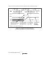
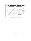
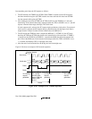
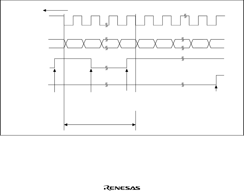
Figure 14.20 shows an example of SCI transmit operation.
Bit 0 Bit 1 Bit 7 Bit 0 Bit 1 Bit 6
Serial clock
Serial data
Transfer direction
Bit 7
TXI interrupt
handler writes
data to TDR and
clears TDRE
bit to 0
1 frame
TDRE
TEND
LSB MSB
TXI interrupt
request
generated
TXI interrupt
request
generated
TEI interrupt
request
generated
Figure 14.20 Example of SCI Transmit Operation


