Rev. 5.00, 09/03, page 563 of 760
17.3 Operation Description
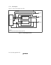
The IrDA module can perform infrared communication conforming to IrDA 1.0 by connecting
infrared transmit/receive units. The serial communication interface unit includes a 16-stage FIFO
buffer in the transmit unit and the receive unit, allowing CPU overhead to be reduced and
continuous high-speed communication to be performed. This module also supports DMAC data
transfer. The IrDA module differs from the SCIF described in section 16, Serial Communication
Interface with FIFO (SCIF) in that it does not include modem control signals RTS and CTS.
Refer to section 16.3, Operation, for SCIF mode operation.
17.3.1 Overview
The IrDA module modifies TxD/RxD transmit/receive data waveforms to satisfy the IrDA 1.0
specification for infrared communication.
In the IrDA 1.0 specification, communication is first performed at a speed of 9600 bps, and the
communication speed is changed. However, the communication rate cannot be automatically
changed in this module, so the communication speed should be confirmed, and the appropriate
speed set for this module by software.
Note: In IrDA mode, reception cannot be performed when the TE bit in the serial control register
(SCSCR) is set to 1 (enabling transmission). When performing reception, clear the TE bit
in SCSCR to 0.
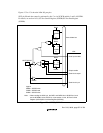
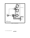
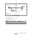
As the SH7709S's RxD1 pin is active-high in IrDA mode, a (Schmidt) inverter must be
inserted when connecting an active-low IrDA module.
The RxD1 pin is active-low in SCIF mode.
17.3.2 Transmitting
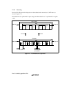
In the case of a serial output signal (UART frame) from the SCIF, its waveforms are modified and
the signal is converted into the IR frame serial output signal by the IrDA module, as shown in
figure 17.5.
When serial data is 0, a pulse of 3/16 the IR frame bit width is generated and output. When serial
data is 1, no pulse is output.
An infrared LED is driven by this signal demodulated to 3/16 width.


