Rev. 5.00, 09/03, page xl of xliv
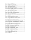
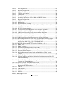
Table 8.2 Pin Configuration.................................................................................................... 183
Table 8.3 Register Configuration............................................................................................ 183
Table 8.4 Register States in Standby Mode............................................................................ 188
Table 9.1 CPG Pins and Functions ......................................................................................... 206
Table 9.2 CPG Register.......................................................................................................... 206
Table 9.3 Clock Operating Modes.......................................................................................... 207
Table 9.4 Available Combinations of Clock Mode and FRQCR Values................................ 208
Table 9.5 Register Configuration............................................................................................ 214
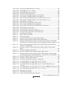
Table 10.1 BSC Pins................................................................................................................. 226
Table 10.2 BSC Registers......................................................................................................... 228
Table 10.3 Physical Address Space Map.................................................................................. 230
Table 10.4 Correspondence between External Pins (MD4 and MD3) and Memory Size......... 231
Table 10.5 PCMCIA Interface Characteristics ......................................................................... 232
Table 10.6 PCMCIA Support Interface .................................................................................... 233
Table 10.7 32-Bit External Device/Big-Endian Access and Data Alignment .......................... 260
Table 10.8 16-Bit External Device/Big-Endian Access and Data Alignment .......................... 261
Table 10.9 8-Bit External Device/Big-Endian Access and Data Alignment ............................ 262
Table 10.10 32-Bit External Device/Little-Endian Access and Data Alignment........................ 263
Table 10.11 16-Bit External Device/Little-Endian Access and Data Alignment........................ 263
Table 10.12 8-Bit External Device/Little-Endian Access and Data Alignment.......................... 264
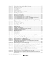
Table 10.13 Relationship between Bus Width, AMX Bits, and Address Multiplex Output....... 279
Table 10.14 Example of Correspondence between SH7709S and Synchronous DRAM
Address Pins (AMX [3:0] = 0100 (32-Bit Bus Width)).......................................... 281
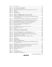
Table 10.15 MCSCRx Settings and MCS[x] Assertion Conditions (x: 0–7).............................. 324
Table 11.1 DMAC Pins ............................................................................................................ 330
Table 11.2 DMAC Registers .................................................................................................... 331
Table 11.3 Selecting External Request Modes with RS Bits.................................................... 347
Table 11.4 Selecting On-Chip Peripheral Module Request Modes with RS3-0 Bits................ 348
Table 11.5 Supported DMA Transfers...................................................................................... 352
Table 11.6 Relationship between Request Modes and Bus Modes by DMA Transfer
Category ................................................................................................................. 361
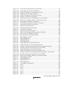
Table 11.7 Register Configuration............................................................................................ 377
Table 11.8 Transfer Conditions and Register Settings for Transfer between On-Chip SCI
and External Memory ............................................................................................. 383
Table 11.9 Transfer Conditions and Register Settings for Transfer between On-Chip A/D
Converter and External Memory ............................................................................ 384
Table 11.10 Values in DMAC after End of Fourth Transfer ...................................................... 385
Table 11.11 Transfer Conditions and Register Settings for Transfer between External
Memory and SCIF Transmitter............................................................................... 386
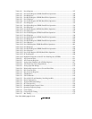
Table 12.1 TMU Pin................................................................................................................. 391
Table 12.2 TMU Registers........................................................................................................ 391
Table 12.3 TMU Interrupt Sources........................................................................................... 405
Table 13.1 RTC Pins................................................................................................................. 409


