Rev. 5.00, 09/03, page 182 of 760
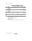
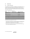
Table 8.1 Power-Down Modes
State
Mode
Transition
Conditions CPG CPU
CPU
Reg-
ister
On-Chip
Memory
On-Chip
Peripheral
Modules Pins
External
Memory
Canceling
Procedure
Sleep
mode
Execute SLEEP
instruction with
STBY bit cleared
to 0 in STBCR
Runs Halts Held Held Run Held Refresh
1. Interrupt
2. Reset
Standby
mode
Execute SLEEP
instruction with
STBY bit set to
1 in STBCR
Halts Halts Held Held Halt
*
1
Held Self-
refresh
1. Interrupt
2. Reset
Module
standby
function
Set MSTP bit to
1 in STBCR
Runs Runs
or
halts
Held Held Specified
module
halts
*
2
Refresh
1. Clear MSTP
bit to 0
2. Reset
Hardware
standby
mode
Drive CA pin low Halts Halts Held Held Halt
*
3
Held Self-
refresh
Power-on reset
Notes: 1. The RTC still runs if the START bit in RCR2 is set to 1 (see section 13, Realtime Clock
(RTC)). The TMU still runs when output of the RTC is used as input to its counter (see
section 12, Timer (TMU)).
2. Depends on the on-chip peripheral module.
TMU external pin: Held
SCI external pin: Reset
3. The RTC still runs if the START bit in RCR2 is set to 1. The TMU does not run.


