Appendix A: Memory and Register Mapping
A-16
AM700 Audio Measurement Set Service Manual
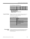
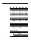
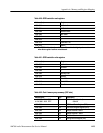
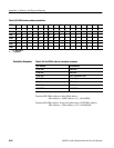
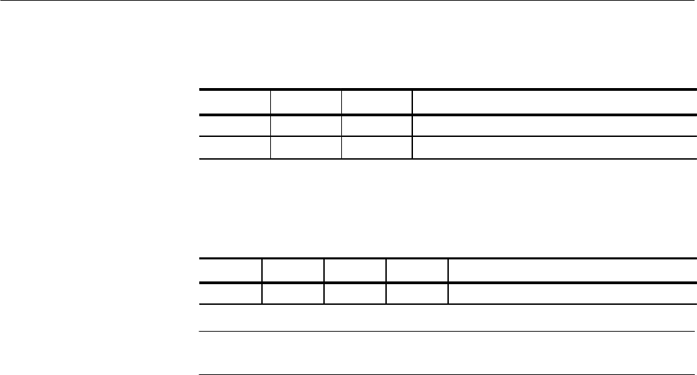
Table A-27: SMOD1 and SMOD0 bit settings (Cont.)
SMOD2 DescriptionSMOD0SMOD1
0 1 0 Generate 8 kHz clock
X
1
1 1 hold
1
X = don’t care.
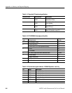
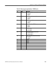
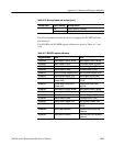
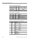
Table A-28: Host interface bootstrap operating mode
Mode MC MB MA DSP initial chip operating mode
7 1 1 1 Bootstrap through the Host Interface (Port B)
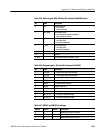
NOTE. Refer to DSP Manufacture’s User Manual for detailed description of the
Bootstrap Operating Mode.
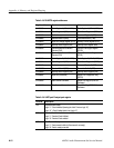
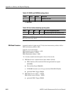
Assumed transfer of eight words (32–bit) from share memory address AS0 to
DSP local memory address AD0.
Count # = # of word transfer
DSP instruction access address = AS0
DMA Source address = AS0+1
DMA Destination address = AD0
* # of word(s) transfer must be equal to factor of four words.
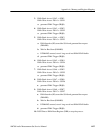
1. DSP Read Access: Address:Source Start Address (SSA0)
a. DMA Interface (DI) stored the SSA0 and generated bus request
(DMABR)
b. Wait for Bus Grant (DMABG)
c. If DMABG asserted, store 4 long words into DMA READ buffer
d. generated DMA Trigger (IRQB)
2. DMA Read Access: SSA1 → SSW0
DMA Write Access: DSA0 ← SSW0
a. generated DMA Trigger (IRQB)
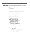
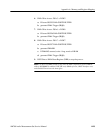
DMA Read Procedure


