Removal and Replacement Procedures
6–66
AM700 Audio Measurement Set Service Manual
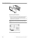
Reverse the procedure to reinstall the LCD Display Driver board.
6. Position the LCD Display Driver board carefully over the standoffs for the
retaining screws.
7. Align the pins of the interboard connector between the LCD Display Driver
and the CPU board.
8. Carefully push the LCD Display Driver down to fully engage the connector
pins.
9. Reinstall the two screws that hold the LCD Display Driver board to the
standoffs on the CPU board.
10. Reconnect the cable from the CPU board to the LCD Display Driver board at
J8.
11. Reconnect the single conductor BRT IN connector at P4.
12. Reconnect the five connectors of the multiconductor cables from the LCD
flat panel display assembly at P1 (two connectors on P1), P2, P3, and P5.
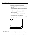
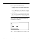
P5 P3P1 P2
P4
J8
J23
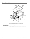
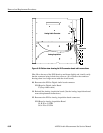
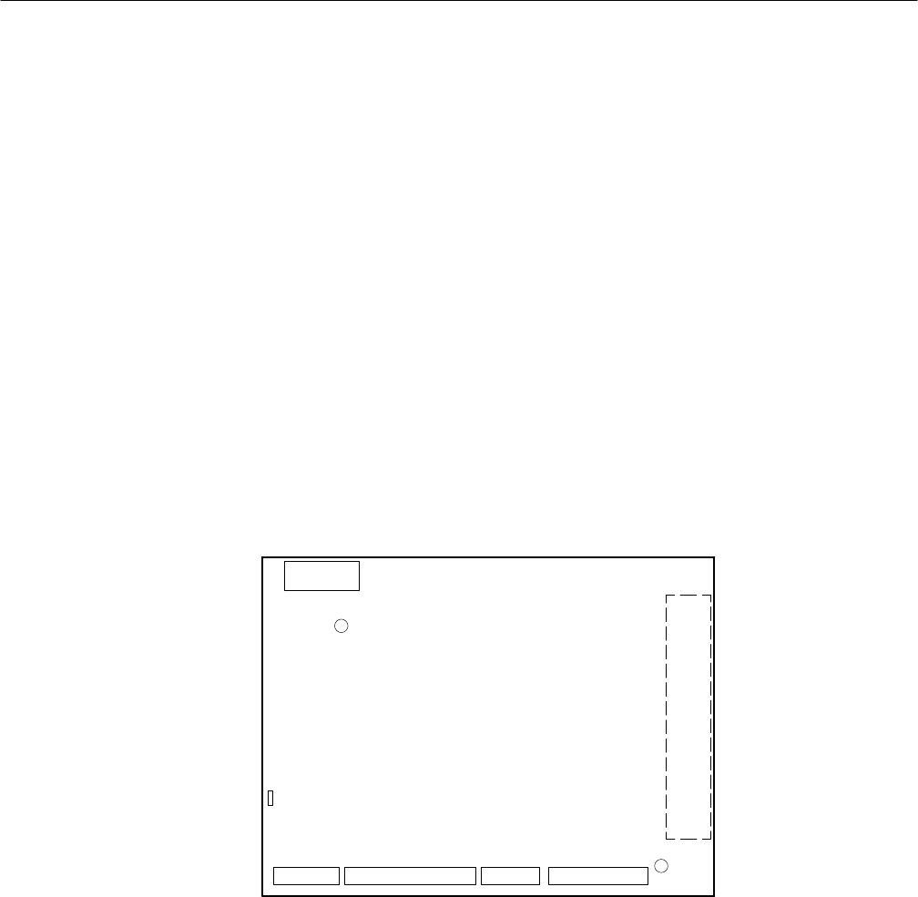
Figure 6–29: LCD Display Driver board with connector locations
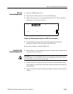
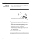
1. Remove the DSP (A7) board (see the DSP removal procedure).
2. Remove the LCD Display Driver (A13) board (see the LCD Display Driver
removal procedure).
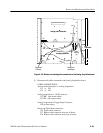
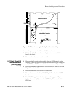
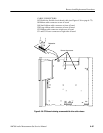
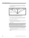
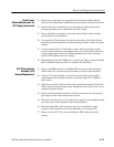
3. Disconnect all cables connected to the CPU board. See Figure 6–30 for the
cable connector locations.
Main/CPU (A6)
Removal/Replacement


