Removal and Replacement Procedures
6–62
AM700 Audio Measurement Set Service Manual
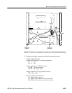
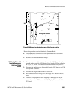
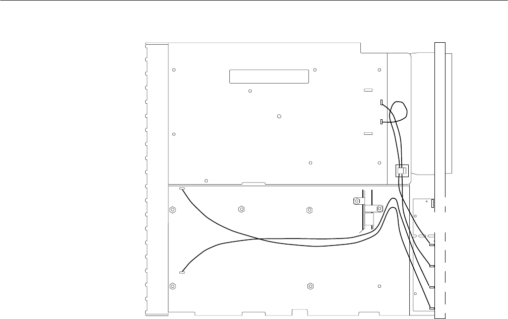
J8
J9
J1
J2
Analog Audio Generator
Analog Acquisition
XLR
Connector
J9
J8
J10
J11
J7
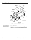
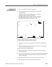
Figure 6–26: Bottom view showing the XLR connector board cable connections
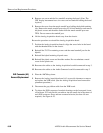
Hint: Move the rear of the XLR board up and down slightly and visually verify
that the connector being locked does not move. (It is locked to the connector
housing when it no longer moves with the circuit board.)
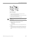
10. Reconnect the XLR to Digital Audio board connector.
XLR Board to Digital Audio Board
J7 (Grey ribbon cable)
11. Reinstall the Analog Acquisition board. (See the Analog Acquisition board
removal/replacement instructions.)
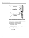
12. Reconnect the XLR to Analog Acquisition board connectors.
XLR Board to Analog Acquisition Board
J11 B IN to J1 CHB
J10 A IN to J2 CHA


