


Adjustment Procedures
5–26
AM700 Audio Measurement Set Service Manual
Digital Audio Board Adjustments
The following adjustments set the control voltage of the phase-lock-loop circuits
and sets the digital generator amplitude.
The following test equipment is needed:
H Digital voltmeter
H Test oscilloscope
H BNC cable, 75 W
H BNC termination, 75 W
H Alignment tool
H Extender cables for Digital Audio circuit board
H Insulated work surface
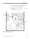
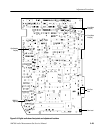
1. The PLL adjustments can be checked with the Digital Audio board installed.
Test points pins are accessible from the side of the instrument with the
cabinet removed. Adjustment of the PLL frequency control coils would not
normally be required unless a repair affecting the frequency determining
components of the oscillators is made.
CAUTION. The following Digital Audio Board adjustment procedure should only
be done by a qualified service person working in an approved anti-static work
station. Adjustments require the removal of the Digital Audio board from the
instrument, and operation with extender cables installed to make the signal and
power interconnections to the AM700.
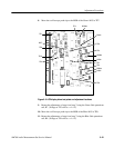
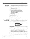
2. With the Digital Audio board removed from the AM700, place the board on
an insulated surface and connect it to the AM700 using extender cables. The
remove and replace instructions are provided in the Maintenance section of
this manual.
Test Equipment Required
Mechanical Setup