Theory of Operation
3–38
AM700 Audio Measurement Set Service Manual
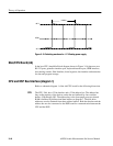
High Resolution mode
High Bandwidth mode
SSI Clock
Frame
BCLK
STD
Channel A Data
Channel A Data
Channel B Data
Channel B Data
SSI Clock
Frame
BCLK
STD
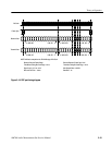
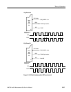
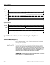
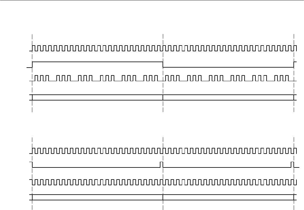
Figure 3–14: SSI clock, frame, B clock, and serial data waveform for High Res and High BW modes
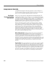
Control and I/O (diagram 2)
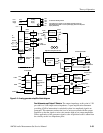
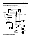
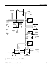
Refer to schematic diagram 2 of the A5 analog generator circuit board for the
following circuit description.
The Serial Control PAL, U87, develops the controlling signals as a stream of
control bits. The control bits are loaded into the Serial Control Register and
latched to the outputs of the register for application to the various devices under
control of the DSP. The serial data stream is buffered by U8 and isolated by U9.
The clocking signal to the Serial Control Register is also isolated, but by U10.
Whenever any control bit changes, the entire register is reloaded.
7-Segment LED. The Serial Control PAL also develops the segment-drive signals
to DS2. This device is available as a diagnostic tool.
Serial Control PAL


