


Adjustment Procedures
AM700 Audio Measurement Set Service Manual
5–19
NOTE. Magnets added to yoke assembly and around the CRT at the factory are
used to square up the corners of the display. The magnets are secured with
silicone adhesive and should not require replacement or relocation under normal
operation. Some careful repositioning of the magnets around the front edge of
the CRT may be required for the best adjustment of the corners of the display.
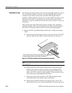
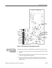
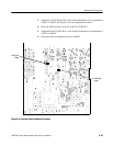
7. If the edges are not flat, observe where geometry adjustment magnets, if any,
are installed on the AM700 chassis around the face of the CRT.
8. Remove any magnet nearest an area that bowing or wowing is excessive. Try
placing a new magnet in the same location with different strength, rotation or
position to improve the geometry.
Some trial and error positioning and placement of the magnets is necessary
to reduce the absolute geometry error (variations in straightness of the sides
and corners of the display) to less than 1.5% or 0.075 inch (1.9 mm)
horizontally and 0.06 inch (1.52 mm) vertically. Because the placement and
rotation of the magnets in combination pulls or diverts the electron beam in a
manner that is not entirely predictable, noting the effect produced by the
different strength of magnet used or location and polarity of the magnet may
help reaching the best combination for good overall geometry.
Magnets specified to use are listed in Table 5–1 at the beginning of this
section.
9. Use clear RTV silicone adhesive to hold magnets permanently. It may take
30 minutes to few hours to set depending on the type of silicone adhesive
being used.
10. This completes the alignment of the replacement display monitor assembly.
Turn off the power and reinstall the equipment cabinet. See the Cover
Removal and Replacement procedure beginning on page 6–55 in the
Maintenance section of this manual for the cover replacement steps.