


9–16
AM700 Audio Measurement Set Service Manual
2
2
W5
W5
W5
W5
Hi BW/(Hi Res)
15,10
1,3,6,8
4,5
16,9
B Hi Res
B Hi BW
Select
U43
A
+22
COM
+15
–15
+5
Floating
Power
Supply
U81 – 83
+
–
U28B
Step Attenuator
6 dB/step
0 to –36 dB
Hi BW/(Hi Res)
Select
0
–6
–12
S2
S3
S4
S8
S1
A
1 of 8
U31
Select
U100
A
+
–
S2
S3
S4
S8
S1
1 of 8
Select
FL
FL
FL
0
–6
–12
Step Attenuator
6 dB/step
0 to –36 dB
1,3
6
8
10
9
5
16
4
15
Mono
A Hi Res
Mute
A Hi BW
Mono
U27B
Mono
Control
Control
Control
Control
Monno/Mute=S1
Power up Mon
+B CH (Mono) is Muted
Lo = Mono
Hi = Isolate
U26
Mono/Mute
Powers up muted
Gain Stage
0,6 or 12 dB
2K
0 or 6 dB Gain
K9
3
+22–22
Output
Ampl 3
U55A
Q29 – 42
24 dB
Gain
Re–Trig
1–Shot
U54A
Gain Stage
0,6 or 12 dB
Output
Ampl 1
24 dB
Gain
Re–Trig
1–Shot
Output
Ampl 4
Output
Ampl 2
0 or 6 dB Gain
K8
+22–22
+22–22
+22 –22
3
To Digital Section
through Opto–Isolators
To Digital Section
through Opto–Isolators
2K
2K
U48A
U95
U27A,U29
OR
U49A,
Q1 – 14
U49B,
Q15 – 28
U55B,
Q43 – 56
CR5
CR5
CR2
CR2
R378
R380
R377
R379
48
Control
Bits
U11,U12,
U32 – 35
Opto–Isolators
U9,U10
Driven by
U8
42 dB
Attenuator
Ro=5 W
42 dB
Attenuator
Ro=5 W
42 dB
Attenuator
Ro=5 W
42 dB
Attenuator
Ro=5 W
R81 – 84
R85 – 88
295
295
295
295
70
70
70
70
K1B
K1C
K10C
K10B
K4C
K4B
K11B
K11C
Out+
Out+
Out–
Out–
To Acquisition
J13
To Acquisition
J14
J8
B CH
OUT
J9
A CH
OUT
VR2
VR1
47V
47V
K7
R16
C3+
Stray
Floating
Gnd
2K
OVL
D
Overload
Monitor
Overload
Monitor
OVL
D
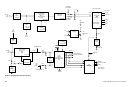
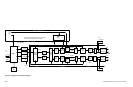
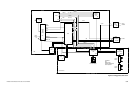
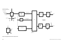
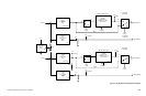
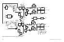
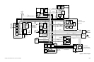
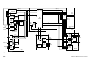
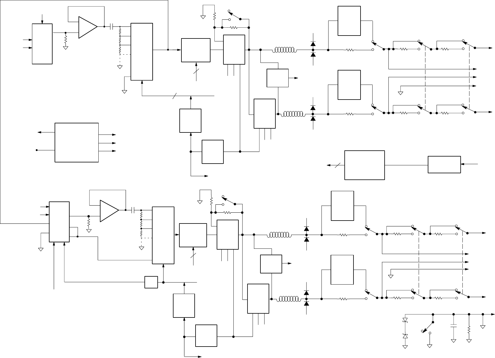
Figure 9–12: Analog Generator output section, attenuators and gain, detailed block diagram