Theory of Operation
AM700 Audio Measurement Set Service Manual
3–9
Converter offset inputs. The high resolution A/D Converter also contains
circuitry to measure and store DC offset and subtract that value form all
readings. This offset value is updated each time a different measurement
application is selected or when requested through the calibration menu.
Unity-Gain
Buffer
Filter
Low-Pass
Filter
Low-Pass
Filter
Low-Pass
Unity-Gain
Buffer
Filter
Low-Pass
Differential
Converter
Differential
Converter
Control
DAC
Offset CAL
CAL-Busy
SCLK
L/R
L/R Serial Data
L Offset
R Offset
L Data
R Data
Convert CLK
L Offset
R Offset
R Offset
R Offset
L Offset
L Offset
Divide
by 4
3.072 MHz
12.288 MHz
20 Bit /
18 Bit A/D
Converter
High Res
A/D
High BW A/D
Clamp
12.288 MHz
12.288 MHz
CH B HIRES
CH A HIRES
CH B HBW
CH A HBW
Control In
Control CLK
Load
12.288 MHz
Xtal
Oscillator
Clamp
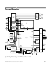
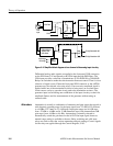
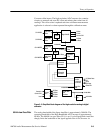
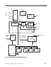
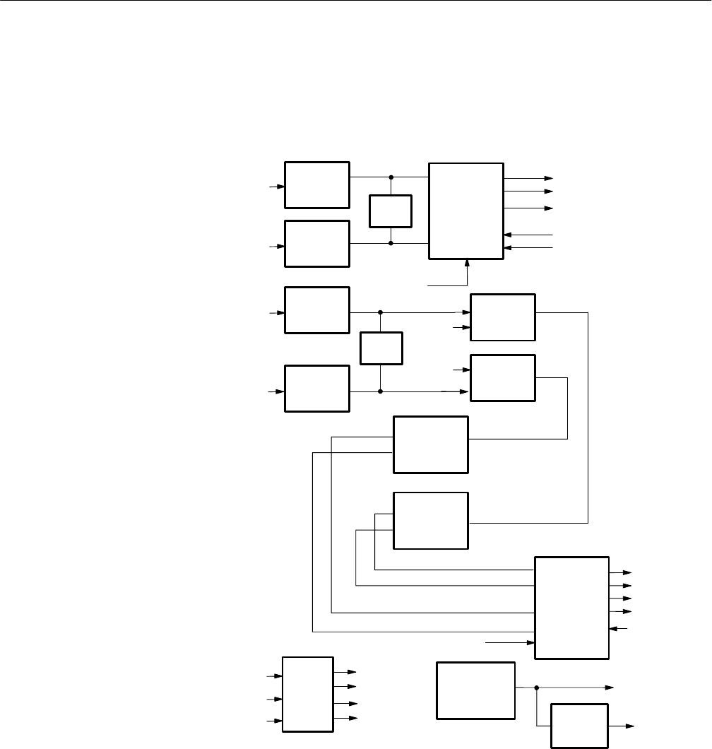
Figure 3–3: Simplified block diagram of the high resolution analog to digital
converter
The analog bandwidth of the Input Amplifier is approximately 300 kHz. The
operating bandwidth of the High Bandwidth A/D Converter is approximately
96 kHz. The 80 kHz low-pass filter, FL10, is an 11-pole filter hybrid circuit that
sharply limits the bandwidth of the signal applied to the A/D Converter. At
80 kHz Low Pass Filter


