


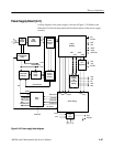

Theory of Operation
AM700 Audio Measurement Set Service Manual
3–73
Each of the secondary output voltages is full-wave rectified and filtered using
choke input filter sections. The +5 V output uses two L-sections; the others use a
single L-section filter.
The + and –15 V regulator pass elements, Q8 and Q9, are complementary, with
Q8 being a P-channel FET and Q9 an N-channel FET. In the +15 V regula-
tor,U8A is referenced to the +5 V developed by U5. Operational amplifier U8B
is referenced to ground. In both, the feedback signal from the output voltage is
still applied to the non-inverting input of the amplifiers. With reduced loading of
the supply, an increasing voltage (more positive on the +15 V or more negative
on the –15 V) decreases the conduction of the pass elements thereby reducing the
voltage. With more loading, the output voltage would tend to decrease and the
operational amplifier output will cause the pass elements to increase conduction
to counter the decreasing output voltage.
This complete linear regulator circuit, operational amplifier U8A and series-pass
element Q8, may be viewed as an operational amplifier circuit with R45 acting
as the feedback resistor and R46 as RIN. The closed loop gain of the circuit is
then set by the ratio of the resistor values. Operational amplifier U8A has its
non-inverting input pin supplied via the feedback resistor from the output of the
series-pass element (the regulated +15 V). A 5 V reference voltage developed by
U7, a band-gap reference device, is applied to the inverting input of U8A, pin 2.
The output level of U8A then follows the feedback voltage and is non-inverted at
this point.
The inversion occurs in the series-pass element, a P-channel FET. With reduced
loading of the supply, an increasing voltage from U8A decreases the conduction
of the pass element, Q8, thereby reducing the output voltage. With more loading,
the output voltage would tend to decrease, and the operational amplifier output
also decreases. This increases conduction in the series-pass element to counter
the decreasing output voltage by suppling more current to the load.
From pin 1 of U8A there is a frequency response limiting feedback circuit
formed by C49 and R47 back to the inverting input of the operational amplifier,
pin 2.
±15 V Regulators