


Theory of Operation
AM700 Audio Measurement Set Service Manual
3–79
The front-panel STBY/ON switch controls the POWER OFF logic signal to the
shutdown circuitry. The master power ON/OFF switch to the power supply is
located on the rear panel of the instrument. When the front-panel STBY/ON
switch is in the ON position, the POWER OFF signal line is pulled low. This
low is inverted by U16D and applied to the Shutdown Logic Gate, U18B, to
allow the PWM to start operating if no other shutdown condition exists.
With the STBY/ON switch is in the STBY position, the POWER OFF control
line is pulled high by R120 back to the +14.4 V supply. This high is inverted by
U16D, and U18B applies a SD signal to the PWM that prevents it from
outputting drive signals to the inverter switching FET.
Also, with the POWER OFF control line high, diode CR45 is forward biased by
the high POWER OFF signal. This removes the /UV LED signal as a control
signal from the PS FAIL LED gate so the PS FAIL LED signal does not go high
with the STBY/ON switch in the STBY position.
Power Supply Failure Warning. A second output developed from U18D is the
/POFF signal. A low /POFF signal forward biases CR31 in the LINE SENSE
input signal line to the Power Supply Supervisor, U9, to pull the line sense input
(pin 5) of that device low. The Power Supply Supervisor then outputs the /PWR
FAIL signal to the main instrument to provide immediate warning that the power
supply is going down. Another input to this same signal line is the RDETECT
signal through CR32 from the PWM, U1. This signal detects when the PWM is
out of regulation and also causes the Power Supply Supervisor to issue the power
failure imminent signal to the main instrument. This warning to the main
instrument also occurs when the master power ON/OFF switch is turned off.
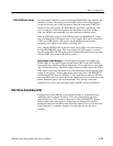
Disk Drive Assembly (A12)
The disk drive of the AM700 is a purchased assembly. It is interfaced to the
AM700 by the Front Panel Processor, U110, and a dedicated floppy disk
controller device, U105, located on diagram 9 of the A6 MAIN/CPU Board.
When reading and writing data to a floppy disk, the floppy disk controller
handles the transfer using DMA after requesting memory access from the Front
Panel Controller. A schematic diagram is not provided for the disk drive
assembly.
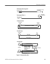
STBY/ON Switch Circuit