


Theory of Operation
3–68
AM700 Audio Measurement Set Service Manual
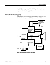
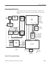
The power supply is an pre-regulator inverter switching supply composed of a
primary rectifier, a housekeeping supply, the inverter switching circuit, output
rectifiers, 15 V regulators, an alarm sensing circuitry that monitors for overvol-
tage, overcurrent, and over temperature conditions, and the alarm logic circuitry
that shuts down the inverter switching circuitry in the event of a problem. Use
diagrams 1 and 2 for assembly A11 to follow the descriptions of the block
circuitry.
Input Power Rectifier. The Input Power Rectifier receives the mains AC voltage
and rectifies it to provide the drive power to the inverter switching circuitry. A
line voltage switch sets the supply to operate on a nominal voltage of either
115 VAC or 230 VAC. On 230 V operation, the primary rectifier acts as a
full-wave bridge rectifier; for 115 V operation, the primary rectifier is configured
as a full-wave voltage doubler.
The primary bridge rectifier is protected by the mains line fuse and surge
suppressors. A mains line filter at the input of the power supply reduces
conducted and radiated EMI from and to the AM700. Additional components in
the rectifier output provide line filtering and common-mode noise rejection for
further reduction of conducted electromagnetic interference. Input surge current
and overvoltage protection components are included in the input rectifier circuit
to prevent major component damage in the event that incorrect line voltage is
applied to the AC input.
Housekeeping Power Supply. A second power supply provides the housekeeping
(or keep-alive) power source. This supply provides power to the logic circuitry
that controls the power supply STBY/ON logic circuitry. It is supplied via a
transformer that is wired with the power line switch to provide the correct
voltage to the primary for either line voltage. The rectifiers for the + and –14.5 V
housekeeping supply are full-wave with capacitive filtering of the rectified
voltages. The filtered voltages are regulated by 3-terminal regulators. Both sides
of the transformer secondary are fused with self-healing fusing devices. One of
the sensing signals (LINE SENSE) to the power supply logic circuitry is
developed from the secondary of the housekeeping supply transformer.
Inverter Switching Circuit. This circuitry comprises the Pulse Width Modulator,
the Power Switching Transistor Drivers, and the Inverter Switching FET that
drive the power transformer.
Output Rectifiers. Secondary outputs of the power transformer are full-wave
rectified and filtered to provide +5 V, +16.5 V, –16.5 V, +22 V, and –22 V. The
+16.5 V and –16.5 V are further regulated to produce the +15 V and –15 V
supplies to the AM700. The source voltage for the Fan Drive circuit is also
provided by the +16.5 V supply.
Power Supply Functional
Block Description