


Theory of Operation
3–28
AM700 Audio Measurement Set Service Manual
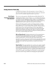
Eye Sampler (diagram 11)
The circuitry of the Eye Sampler is an equivalent time sampler used in the
generation of the eye pattern and measurement of the jitter waveform. Either the
incoming Eye Source or the phase error signal is selected for application to an
A/D converter. The 8-bit parallel output of the A/D converter is applied to the
Eye Sampler PAL where the equivalent time samples are chosen as 1 of 27 input
samples. The samples are taken at 127 different phases of the input data to
provide an envelope of samples that describe the incoming waveform when
reconstructed. The outputs of the Eye Sampler are applied to the data formatter
PAL (diagram 3) for formatting before being sent to the DSP by the Sample
Transmitter.
A phase-lock loop (PLL) circuit generates the clock signal for the Eye Sampler.
The INMCK signal (Input Master Clock) at 256 times the sample rate is applied
to the phase comparator of the PLL. The PLL track the slow rate changes of the
master clock. The faster changes that occur in the master clock (derived from the
applied audio signal) is jitter. The control voltage to the VCO is filtered by an
active low-pass filter circuit and buffered by a operational amplifier for
application to the A/D converter when measuring jitter. With a low-jitter
waveform, the amplifier gain may be switched from unity to X8 gain to increase
the jitter amplitude for better digitization.
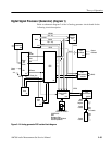
Auto Equalization (diagram 12)
The Auto Equalization circuitry provides a controllable amount of peaking to the
leading edge (or top) of the digital square-wave signal. Rolled off signals are
peaked to produce a flatter top signal while peaked signals are rolled off to
produce a flatter top signal.
The input signal is applied to a low-pass filter circuit to remove the high
frequency components. This removes any noise glitches from the signal and
provides a uniform rolled off signal for processing. There are two variable gain
stages used in the circuitry. The first is part of an AGC circuit to maintain a
controlled signal amplitude. The second variable gain stage provides the gain
versus frequency characteristics that are used to flatten the digital square-wave
signals. The peaking amplifier adds its output to the signal based on the amount
of roll-off or peaking of the input signal. If the input signal is a very good flat
signal, no added roll-off or peaking is added by the variable gain stage.