


Theory of Operation
AM700 Audio Measurement Set Service Manual
3–61
Front Panel Board (A9)
The Front Panel board has the user interface buttons and touch screen circuitry.
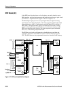
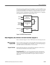
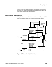
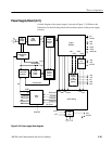
Control Register, Knobs, Beeper, and Resistive Touch Panel (diagram 1)
Diagram 1 shows the control register, the knob control circuitry, the beeper, and
the resistive touch panel.
The control register is formed by a series of shift registers that hold a total of 128
bits. These bits are loaded from the front-panel processor through U11A, The
serial data, clock, and latch signals are all generated by the front-panel processor.
When bit value changes are made by the front panel processor, the entire 128 bits
are reloaded serially into the register string. The register string holds the control
and readout bits of the touch panel, the large and small rotary knobs, the panel
LED indicators, and all the front-panel buttons.
A change in state of the bits from the initial state caused by a front-panel control
change (knob, touch panel, button press, etc.) is determined when the 128 bits
are read back to the front panel processor through U11B. To increase throughput,
the new data bits are loaded into the registers as the stored data bits are read out.
The location of specific bits in the serial stream is fixed by the clock and latch
signals generated by the front-panel processor. Not all 128 bits are used in the
data stream. Unused bits are “don’t care” and ignored by the front panel
processor.
The three rotating control knobs are continuous rotation, 2-bit rotary encoders.
Their position and rotation information is grey-scale encoded. The A and B
outputs of the encoders are square waves that are 90° phase shifted from each
other. In the clockwise direction of rotation, the A output positive transitions
leads the B output positive transitions. For counterclockwise rotation, the B
output leads the A output.
An internal circuit in the PALs counts the number of transitions to determine the
amount of rotation of the knobs, and the relative phase relationship between the
A and B outputs indicates the direction of rotation. The Rotary Encoder PALs
decode the information from the knobs into an 8-bit parallel data word. That data
is applied to the parallel inputs of the serial shift registers in the PALs to become
part of the 128 bit serial data stream.
The 2.2 kHz beeper is controlled by a signal from the front panel processor. That
signal, TOUT1, is turned on for a short length of time to indicate a touch (a short
click) or a longer time to produce a warning alarm.
Control Register
Front Panel Knobs
Beeper