


Diagnostics
AM700 Audio Measurement Set Service Manual
6–41
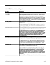
16. Set I/O mode and initialize the I/O interface hardware.
a. Write “.0” on the diagnostic LED display.
b. Write 16 to step code (in Boot RAM).
c. Set the Dio Infc to use the appropriate I/O mode.
d. Call the Dio Infc initialization function to setup the I/O hardware.
17. Initialize the smart exception handler.
a. Write “.1” on the diagnostic LED display.
b. Write 17 to step code (in Boot RAM).
c. Switch exception vector handling from the dumb handler to the smart
one.
d. Set handler modes to generate long exception reports and terminate.
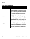
18. Do application-specific hardware initialization.
a. Write “.2” on the diagnostic LED display.
b. Write 18 to step code (in Boot RAM).
c. Call an application hardware initialization routine, which will:
Disable bus error reporting.
Write the default value (0x010560cc) to the DSP ASIC. Address
Holding Register, so it can’t be accidently changed.
Setup the Video ASIC for the AM configuration.
If using serial I/O, clear the instrument screen memory.
Restore bus error reporting.
19. Do an application-specific boot.
a. Write “.3” on the diagnostic LED display.
b. Write 19 to step code (in Boot RAM).
c. Call the boot function found in step 15.
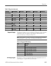
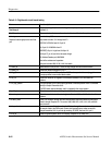
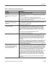
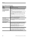
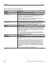
Digital Audio Board Semiautomated Testing
This information describes a set of tests used to perform a semiautomated test of
the digital audio board. These test, shown in Table 6–11, are done at the factory
or customer service using an AM700 work station with the proper test equipment
and test programs to run the checks on the AM700.