Rack Adapter Instructions
6–100
AM700 Audio Measurement Set Service Manual
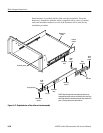
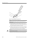
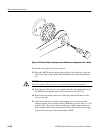
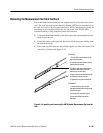
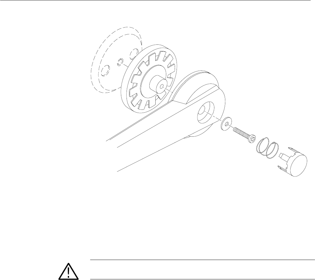
Figure 6–53: Removing the retaining screws holding the swing arms to the cabinet
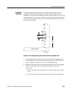
11. Pull the rack adapter to its full extension.
12. Place the AM700 into the adapter and position it fully forward to align the
holes in the sides of the adapter with the handle holes of the measurement
set.
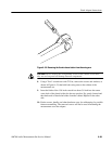
CAUTION. Do not use the long screws removed from the measurement set to
attach the adapter. The long screws can damage the internal components.
13. Install the short Torx head screws supplied with the rack adapter kit to hold
the AM700 to the adapter using a Torx screwdriver with a T15 tip.
14. Release the stop latches on the rack slides and push the instrument all the
way into the rack.
15. At the rear of the rack, install the instrument power cord and any other
cabling required, such as printer cables, GPIB remote control cable, or VGA
monitor cable. This may be done from the front with the measurement set
fully extended on the tracks to make sure all the cables will be long enough
to permit full extension of the rackmounted AM700.


