


AM700 Audio Measurement Set Service Manual
A-1
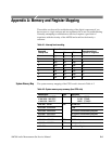
Appendix A: Memory and Register Mapping
These tables can be used for troubleshooting of the digital components if you
have access to a logic analyzer and are experienced in its use for troubleshooting.
Normally, attempting to troubleshoot to this level requires a good deal of
experience with the circuitry of the AM700 and would not be done by a
customer.
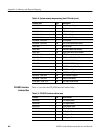
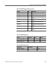
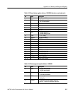
Table A-1: Interrupt level encoding
Control line status
Requested
interrupt level
IPL2
IPL1 IPL0
Interrupt mask level
required for recognition
0 High High High N/A
1 High High Low 0
2 High Low High 0-1
3 High Low Low 0-2
4 Low High High 0-3
5 Low High Low 0-4
6 Low Low High 0-5
7 Low Low Low 0-7
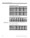
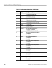
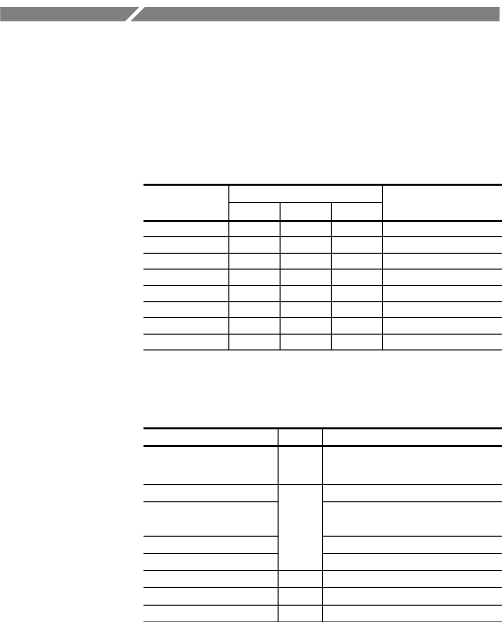
The system memory mapping of the CPU board is shown in Table A-2.
Table A-2: System memory map summary (host CPU side)
Address (hex) Type Description
a. 0000 0000 – 000F FFFF
b. 0000 0000 – 0007 FFFF
c. 0000 0000 – 0003 FFFF
R PROM 1 MB (C4096)
512 KB (C2048)
256KB (C1024)R
0400 0000 – 040f ffff R/W NVRAM 1MB
0C00 0000 – 0CXX XXXX VRAM
0D00 0000 – 0DXX XXXX I/O Processor Shared Memory/Registers
0E00 0000 – 0EXX XXXX I/O Processor Shared Memory/Registers
0F00 0000 – 0FXX XXXX LANCE
1000 0000 – 1000 00XX R/W RS232 Interface
1100 0000 – 1100 00XX R/W At Keyboard Interface
1200 0000 R Board Status Register
System Memory Map