


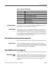
Theory of Operation
AM700 Audio Measurement Set Service Manual
3–59
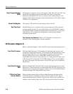
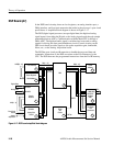
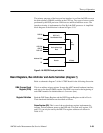
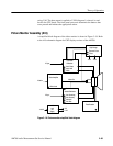
The primary purposes of the host port bus interface is to allow the DSP to access
the main memory (DRAM) resident on the CPU bus. Two types of access can be
performed by the DSP processor: DMA access and Host Interface access. The
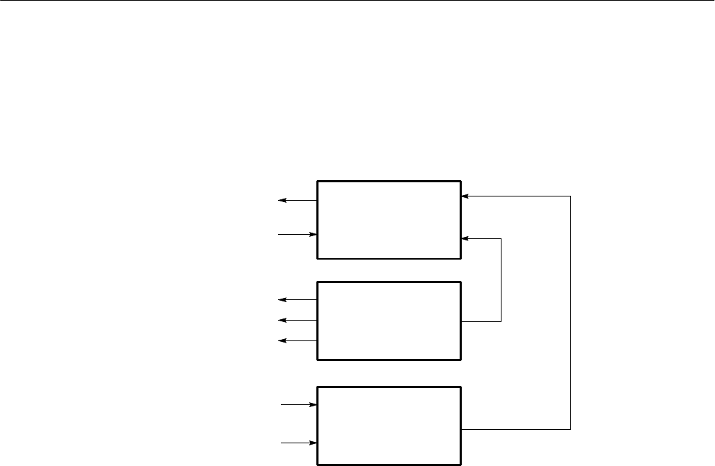
interface circuitry is implemented on Port B of the DSP processor. A simplified
block diagram of the functions is shown in Figure 3–18.
DSP BG
DSP BB
DSP R/W
DSP TS
DSP HEN
Addresss CPU
TS
Bus
Ready
Hi Ready
Decoder
DSP Port B
Bus Arbitration Block
Host Interface Logic
Block
Figure 3–18: DSP/CPU host port interface
Board Registers, Bus Arbitrator and Audio Serializer (diagram 7)
Refer to schematic diagram 7 of the A7 DSP board for the following discussion.
This is an address trigger register. It resets the ASIC internal hardware interface
and sets up for the next DMA transfer. The PRR is accessed at the beginning of
each DMA transfer. Its default address is 5xxxxxxx (hex).
Both the DSP Status Register and the DSP Program Register reside in Port A.
Their functional definitions are described as follows.
Status Register (SR). This is one of the two hardware register implemented to
indicate various hardware status on the DSP side. This read-only register, U52
and U53, can only be read by the DSP. The register addresses are shown in
Table A-25.
DMA Process Reset
Register (PRR)
Register Definition