


Theory of Operation
3–16
AM700 Audio Measurement Set Service Manual
User Controlled Audio Data Parameters. The user can set the following software
controlled audio data parameters for the digital signal generator: waveform,
frequency, amplitude, audio sample rate, number of bits, dither, channel status,
and user bits. Changes to these signal parameters involve no hardware beyond
that required to communicate from the CPU to the Digital Audio Board.
The hardware supporting the normal operation of these functions consist of the
following circuitry blocks:
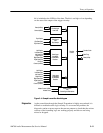
H Power Input. Power to the digital audio board is supplied through the cable
connected to J30. The +5 V source is protected by an on-board 2 A fuse.
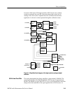
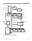
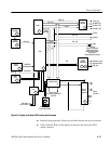
H DSP Core. The DSP core circuitry is composed of the DSP chip, and address
decoder, a random-access memory SIMM, and the host interface buffers. A
simplified block diagram of the DSP core is shown is Figure 3–6.
H Clock Sources. There are two clock sources to the DSP. A crystal clock
circuit supplies a 12.288 MHz OSC signal to the timing generator PAL
circuit that produces the DSP clock signal. That clock signal is multiplied by
the DSP to provide an internal DSP clock of 39.74 MHz. The second clock
is a differential clock signal from the Analog Acquisition circuit board on
J31 pins 39 and 40. It is a more accurate 12.288 MHz clock that provides the
digital generator output timing.
H DSP Resets. The reset to the DSP is a combined reset signal: the power-on
reset and a reset from the CPU. At power up, the DSP is held in reset until
the power and PLL has stabilized. The active low reset from the CPU is
applied to the Digital Audio board on J31 pin 33.
When the reset (DSPRST) is asserted (low), the DSP is initialized and held
in the reset state until the reset line goes high. This reset signal is widespread
on the Digital Audio board.
H Host Port. The CPU and the DSP communicate through the host interface on
J31. Two buffers between the CPU and the DSP isolate the two devices from
each other when they are not communicating. One buffer isolates the control
signal and the second is a bidirectional parallel data buffer.
H Interconnection Cables. The power cable on J30, the host port cable on J31,
the rear panel cable on J27, the sample transmitter cable on J32, and the front
panel cable on J29 provide the interconnections to and from the Digital
Audio Board. Check that they are properly seated and securely connected.
H Variable interface clock phase. Main output phase changes with respect to
Ref output phase.