Diagnostics
AM700 Audio Measurement Set Service Manual
6–45
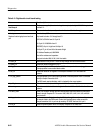
Table 6–11: Digital audio circuit board testing (cont.)
Test name Test description
Test group 2 Generator adjustments and functional checks.
2.10 adj_gen_lvl This test sets the generator for normal operation while the operator adjusts R483, GEN
LEVEL for 1 Vpp output into 75 ohms.
R483 sets the reference level on gain dac U107. This sets the current in the Q7/Q8
switch and thus the voltage swing on R246. The ttl AES_OUT signal from U108 pins 36
and 39 steers the current through either Q7 or Q8. The signal on R246 is then amplified
by U72 and scaled by R150 and R461. It is sent as UNBAL_OUT to the rear panel board,
where it is further scaled by fixed resistors.
2.11 cable_simulator This test switches on the cable simulator so the operator can check for rise time of 100
ns to 200 ns at TP18.
The cable simulator consists of R152, R156, C42, C34. It is switched into the circuit by
U71 when pin 6, RED_BW_SEL is low. RED_BW_SEL is controlled by the 56k through
the serial control output, U141 pin 3.
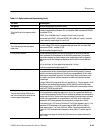
2.12 phase_shift_range This test exercises the phase shifter part of the generator pll. While the operator watches
to see that phase shift is actually occurring, the test checks that the pll stays locked as
the phase is shifted.
Most of the functionality for this test is contained in U104. When the 56k writes a phase
shift value to U104, it signals U105 through pll_setl (U104) to put the loop into “slow”
mode by switching off Q18 and Q19. The new phase value is then applied to the counters
internal to U104 and the loop “slowly” shifts to the new phase. Since the step in phase is
kept small, the loop stays locked. When the loop settles at the new phase value, it
returns to non-slow mode.
Test group 3 Receiver tests, Generator tests which require the receiver.
3.1 adc_zero This checks operation of the slow adc U137 by programming it to measure one of its
grounded inputs, and checking that the returned value is within 5mV of ground.
U137 gets its reference from U138. It requires a continuous clock which it gets through
CLK1536 from U115 pin 14. It communicates serially with the 56k through three control
lines, (ADC), SCCLK, and SCTD which come from U117 pins 26, 14, and 31, respec-
tively.
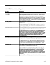
3.2 input_level_cal This test internally connects the generator to the receiver and varies the generator output
level to check that the input level measurement is within range.
The input level is determined by measuring the control voltage in the agc loop. U109
selects the LOOPBK input which is buffered by U75, amplified by variable-gain amp
U110A, and amplified more by U111. The output of U11 is peak-detected by CR22 and
CR23, and the resulting dc level is balanced against the –12 V supply by divider R259
and R260. If the peak value exceeds about +2.5 V, integrator U112’s output moves
downward reducing the gain of U110A. In this way, the voltage at U112 output represents
the gain needed to keep the peak of the agc’d signal at 2.5 V. This voltage is measured
by the slow adc.
Input selector U109 is controlled by four outputs from the serial control chain.


