


Theory of Operation
3–60
AM700 Audio Measurement Set Service Manual
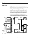
Program Register (DPR). The program register, U54 and U62, indicates various
board status and control various board operations on the DSP side. Its contents
can be written and read. It must be initialized by writing FFFFFFFF (hex) to the
DPR after power-up or after a system reset has been active high. The register bits
are defined in Table A-26.
The function of the audio serializer, U49, is to provide two 16-bin serial data
streams to drive the DAC that resides on the front-panel board. It is dual 16-bit
parallel to serial converter. There is a 32-bit data register that can be accessed by
the DSP to read (for diagnostic purposes only) or write the channel DACs. The
upper 16 bits [bits(31 .. 16)] of data drive the right channel DAC. The lower
16 bits [bits(15 .. 0)] of data drive the left channel DAC.
To read back the data stored in the register by the DSP, SMOD1 and SMOD0
must be set to 1 prior to a read access by the DSP.
This circuitry times the access to Port A and outputs the AFAULT IN flags as a 0
if an access fault is detected.
This register, U56, decodes the inputs to provide the hardware level version
number. This PAL also outputs a level trigger (IRQC) to the interrupt register.
The possible conditions that initiate the IRQC interrupt are shown in Table 3–3.
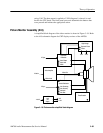
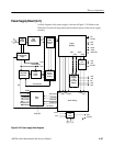
Digital Signal Processor (diagram 8)
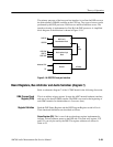
The Interrupt Inputs and their respective sources are given in Table 3–3.
Table 3–3: Interrupt inputs and sources
Interrupt input Type of interrupt Interrupt source
IRQA edge Speaker Signal Interrupt
IRQB edge DMA Trigger
IRQC level Port A Bus Error Interrupt
level Port B Bus Error Interrupt
level Sample Receiver 0 Interrupt
level Sample Receiver 1 Interrupt
Serializer
Bus Timer
Version Number Pal
DSP Interrupts Inputs
Functional Description