


Theory of Operation
3–76
AM700 Audio Measurement Set Service Manual
VR1, resistor R79 provides the necessary drop to keep VR1 properly biased
within its current limits. The result this circuit arrangement produces is that
while the voltage divider sets the proper level on pin 5 of the comparator, any
change in the +5 VI current sense level is transferred fully to the comparator; the
junction of R78 and R80 follows the full voltage change because that is what the
voltage drop across R79 is doing. Another difference is that the + input of U11A
is connected to the +5 V supply through a single resistor rather than a voltage
divider circuit as in the other overcurrent sense comparators.
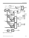
The temperature sensing elements also provide input to the Over Temp Indicator
Comparator, U10B, the Over Temp LED comparator, U10A, and the Over Temp
Shutdown Comparator, U17B. The over temperature indicator circuit provides an
advance warning that the temperature is too high, in advance of an actual over
temperature shutdown.
Over Temperature Comparators. Resistors R118, R117, and R116 set up slightly
different references to the comparators with the same reference applied to both
U10A and U10B. When the voltage at the common inputs to the comparators
drops to about 5.4 V, the output pin of comparators U10A and U10B will drop
and DS10, the internal over temp LED, is turned on. That low is inverted by
U28E and applied to the Over Temp LED signal line. That signal is read by the
CPU and an over temperature warning message will be displayed. The user will
then have a visual indication that an over temperature condition exists. The
output of U13B is the /OVERTEMP signal that provides the CPU with an over
temperature warning that causes a warning message to be shown in the display.
If the temperature continues to rise, the comparator input voltage continues to
decrease. At about 4.4 V, the power supply temperature is high enough that a
shutdown is necessary. At that point the output of U17B goes low and sends the
over temperature alarm to U18A in the shutdown logic circuitry. Negative-logic
NOR gate U18A (any low in gives a high out) also has the /OVERVOLTS signal
from the Power Monitor, U9, as an input.
Shutdown Logic. A high output from U18A due to either an over voltage
condition or an excessive over temperature condition fires SCR Q13 and applies
a low to the shutdown gate U18B and the PS FAIL LED gate U18C. Once fired,
the SCR latches the circuit in the shutdown state until the power supply is
completely turned off to remove the housekeeping supply voltages.
The Shutdown Logic gate, U18B, has an input from U18A that is the combined
over voltage and over temperature shutdown signal; an input from U17A that is
the over current shutdown signal, combined from all the over current sensing
circuits; and an input from U16D from the front panel STBY/ON switch. Any of
these inputs going low generates a high SD (shutdown) signal to the Pulse-Width
Modulator to turn off the switching signals to the Inverter FET.
Alarm Logic