


Theory of Operation
3–6
AM700 Audio Measurement Set Service Manual
CAL In
XLR
Input
Differential Input
Amplifier and
Gain Select
Tunable
Notch
Filter
To High Bandwidth A/D
To High Resolution A/D
Termination
Select
Auto
Range
Underrange
Overrange
Protection
Clamp
Input
Attenuator
EMI Filter
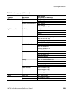
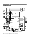
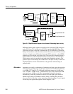
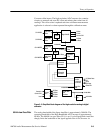
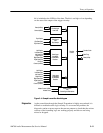
Figure 3–2: Simplified block diagram of one channel of the analog input circuitry
Differential analog audio signals are applied to the front panel XLR connectors
on the XLR board, A2 and passed to the CHA input through EMI filters. The
CHA input provides a selection of terminations of 150 W, 600 W, or 200,000 W.
Relays are switched to make the selection under firmware control. There is also a
selection of signal source. Either the front-panel XLR connector or the AM700
generator may be selected, also using relays. If an excessive amplitude signal is
applied while one of the termination resistors is being used, an overload sense
circuit causes a relay to open the circuit path to the termination resistors. The
generator input is used during auto-calibration of the input circuitry to check for
amplitude flatness and for measurements of the generator without using an
external cable.
Attenuation is actually a combination of attenuator and gain stages that provide a
wide dynamic operating range for the input signal from –22 dBu (62.5 mV
RMS
)
to +44 dBu (125 V
RMS
) in 12, 6-dB steps. Input gain ranges are in 6 dB steps
from –22 dBu to +8 dBu and in 12 dB attenuator steps (with intermediate 6 dB
gain steps) from +8 dBu to +44 dBu. Autoranging is normally selected to
automatically switch the gain based on the level of the input signal, however,
manual range setting is available to the user. Relay switching and solid-state
relays are used to select the various attenuation and gain settings. Control signals
for the relays are applied through the Control Register, U103.
Attenuators