


Performance Verification
4–2
AM700 Audio Measurement Set Service Manual
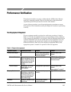
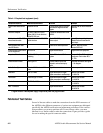
Table 4–1: Required test equipment (cont.)
Equipment required ExamplePurposeMinimum specification
Digital Audio Measurement
Set
Tektronix AM700 Provide digital audio test signals
and measure digital audio test
signals
Tektronix AM700 Audio Measure-
ment Set
Personal Computer PC-DOS or MS-DOS 3.0 or
higher, 386, 3.5 inch disk drive.
Serial RS-232 port.
Provide for remote control of the
AM700.
Serial printer with RS–232C
interconnection cable
24-pin dot matrix with RS-232C
serial interface
Check RS–232C operation serial
printer output
Epson LQ series serial printer or
Hewlett-Packard LaserJet with
serial input.
GPIB controller with stan-
dard GPIB cable
Check GPIB remote operation Guru II+ Tektronix product
number S3FG100
Interconnection audio cables
for test equipment.
XLR to XLR Signal interconnection Supplied with test equipment
Impedance Transformer 110 W to 75 W impedance
matching
Match AES ref out to 75 W
system
Canare 110 W to 75 W matching
transformer. Part number BCJ–
XJ–TRA
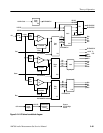
Interconnection Cables See Figure 4–1 Connect AM700 inputs and
outputs to various test equip-
ment.
Customer fabricated. See Figure
4–1 for diagram.
Audio Cables (2) Standard XLR female to XLR
male
Signal Interconnection Customer provided
Attenuator 10X 75 W BNC Signal attenuation for digital
signal connection to oscilloscope
Tektronix part number
011-0061-00
Termination Feed through 75 W BNC Signal termination for digital
signal connection to oscilloscope
Tektronix part number
011-0103-02
Termination 75 W BNC, 0.025% Signal termination Tektronix part number
011-0102-01
BNC T connector Signal interconnection Tektronix part number
103-0030-00
1
A Tegam TM500 or TM5000 power supply is required to power the plug-in module.
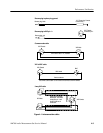
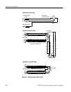
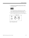
Fabricated Test Cables
Several of the test cables to make the connections from the XLR connectors of
the AM700 to the different connectors of various test equipment are fabricated
specifically the AM700 verification and adjustment procedures. If the verifica-
tion procedures you want to perform call for one of these cables, you must
fabricate it or a similar cable to make the connections. Figure provides a guide
for use in making the special connector cables.