Removal and Replacement Procedures
AM700 Audio Measurement Set Service Manual
6–87
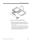
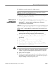
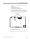
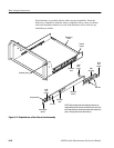
5. Disconnect the four connectors at the left front of the power supply board.
CONNECTORS:
J11 A two-wire connector to the fan.
J5 Ribbon cable to J48 on the CPU board.
J10 A two-wire connector to the display monitor board
J6 A two-wire connector to the Stby/On switch.
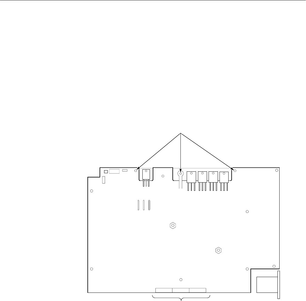
6. Use a T-10 Torx screwdriver to remove the five screws holding transistors
Q2, Q3, Q6, Q7, and rectifier CR26 to the heat sink on the left side of the
power supply board. Do not remove the screws at either end of the heat sink
as these hold the heat sink bar to the circuit board (see Figure 6–44).
Power connectors
Do not remove these screws.
J6
J10 J5 J11
CR26
Q2Q3Q6Q7
EMI Line
filter
Figure 6–44: Power supply connector locations
7. Remove the two P1 cross-tip screws that hold the EMI line filter to the rear
chassis.


