


Specifications
AM700 Audio Measurement Set Service Manual
1–15
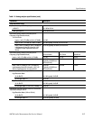
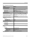
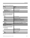
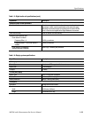
Table 1–5: Digital audio unit specifications (cont.)
Capabilities Description
DSP 15-pin D, TTL/CMOS compatible. Pinout is compatible with Ariel Digital
Microphone.
Input and Output Impedances
Digital In, Digital Out, Digital Reference In,
Digital Reference Out
110 W ±10%, 0.1 MHz to 6 MHz
Unbalanced In, Unbalanced Out 75 W ±5%, 0.1 MHz to 6 MHz
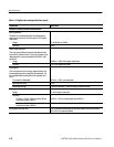
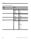
Input and output levels
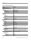
AES/EBU I/O Levels
Input levels required for normal operation and the output
levels available. For details on measured or program-
mable parameters, see either Main Receiver Interface
Parameter Measurements or Generator Variable
Parameters.
Digital In 0.15 V to 10 V peak-to-peak
Unbalanced In 30 mV to 2 V peak-to-peak
Digital Reference In 0.2 V peak-to-peak minimum eye opening. 10 V peak-to-peak maximum
amplitude, 20% minimum eye height
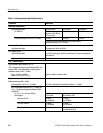
Digital Out Programmable from 0.2 V to 8 V peak-to-peak into 110 W
Unbalanced Out Programmable from 50 mV to 2 V peak-to-peak into 75 W
Digital Reference Out Fixed at 5.4 ±0.5 V peak-to-peak into 110 W
DSP I/O Levels
DSP Inputs Vil = 0.8 V, Vih = 2 V, Iil = 4 mA, Iih = 0 (CMOS with 1.2 kW pull-up)
DSP Outputs Iol = 4 mA, Ioh = –5.3 mA, Vol = 0.6 V, Voh = 2.4 V
Optical I/O Levels Conforms to TOSLINK parameters
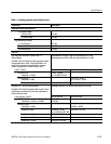
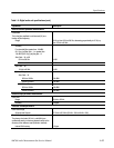
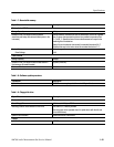
Receiver interface parameter measurements
Main Input Level
This is the level in Volts peak-to-peak being applied to
the selected digital input (the front-panel Digital In or
rear-panel Unbalanced In).
Measurement Range XLR: 0.15 V to 8.0 V peak-to-peak
BNC: 30 mV to 2.0 V peak-to-peak
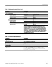
Accuracy with Factory Calibration Factors XLR: ±(30 mV + 15% of reading)
BNC: ±(15 mV + 15% of reading)
Clock Rate
Range All inputs: 30 kHz to 52 kHz.
Accuracy ±10 ppm