


Maintainence
AM700 Audio Measurement Set Service Manual
6–7
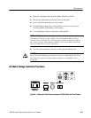
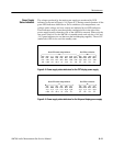
Signals and power supply voltages are passed through the instrument by a
system of interconnecting cables. The connector holders and cables are keyed to
prevent incorrect installation in most cases. A triangular key symbol is used to
identify pin 1 on the circuit board to assist in aligning the correct pins on the
mating connector.
Corrective Maintenance
The following procedure is designed to assist in isolating problems, which in
turn expedites repairs and minimizes down time.
1. Ensure that the malfunction exists in the instrument. This is done by making
sure that the instrument is operating as intended by Tektronix (see the
Operating Instructions) and by checking that all connected signal sources are
actually providing a signal. Use the generator to analyzer internal routing
capability of the AM700 to verify that the AM700 is operating correctly.
2. Determine the nature of the problem. Attempt to make the determination of
whether the instrument is out of calibration or if there has been a component
failure. Once the type of failure has been determined, proceed on to identify
the functional area most likely at fault.
3. Visually inspect the suspect assembly for obvious defects. Check for broken
or loose components, improperly seated components or cable connections,
overheated or burned components, chafed insulation, and other visible
defects. Reseat any obvious loose components or connectors and replace or
repair defective cables. Overheated components indicate a serious problem.
A defective assembly requiring repairs should be repaired using the Board
Exchange Program (if the assembly is available in the exchange program).
4. Repair to some defective assemblies is supported by a board exchange
procedure. Component-level repairs should not be attempted by the user as
damage to an assembly by a non-Tektronix service person will void the
warranty. The result is full board cost for repairs instead of the more
economical board exchange. The circuit board assemblies are assigned
assembly numbers for identification in the instrument and for ordering
replacement assemblies. Removal and replacement procedures for the
assemblies are found later in this section of the service manual. Refer to
Board Exchange Program on page 6–49 for information of the exchange
program.
Major Assembly
Interconnection