


Removal and Replacement Procedures
6–68
AM700 Audio Measurement Set Service Manual
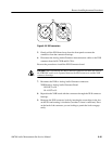
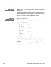
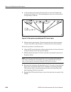
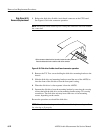
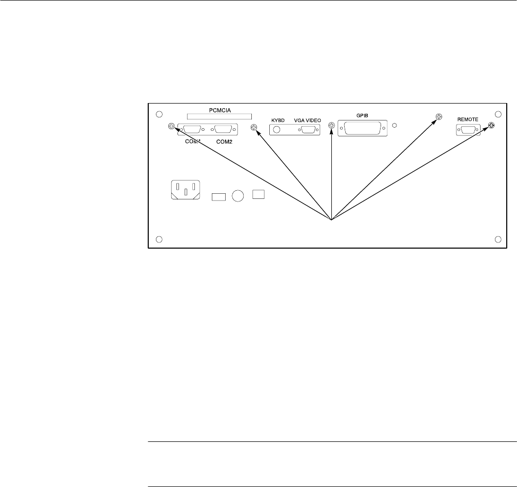
4. A total of eight screws need to be removed. Five screws are found on the
rear panel; see Figure 6–31. The remaining three screws are on the board in
close proximity to the fan.
CPU Screws
Figure 6–31: Rear panel screws holding the CPU board in place
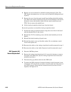
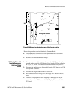
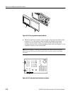
5. Slide the board approximately 1/8-inch towards the front of the instrument
so that it clears the six plastic latches. Lift the board off of the instrument.
Reverse the procedure to install the board.
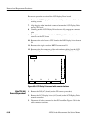
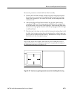
6. Align the CPU board latch holes with the plastic latches and lower the board
to align it with the slots in the top of the latches.
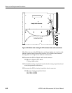
7. Slide the board back about 1/4-inch to catch the circuit board in the slots of
the plastic latches.
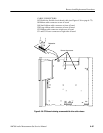
NOTE. The disk drive interconnection cable is easy to capture underneath the
CPU when reinstalling the board. Make sure it is positioned above the board
edge so that it may be reconnected when the CPU board is in place.
8. Reconnect the connectors disconnected in step 3. It is easier to leave the hold
down screws out until the cable are all connected to ease board placement.
This holds the cables in position and prevents them from interfering with
board alignment with the screw holes.
9. Reinstall the CPU board hold down screws in the board and rear panel of the
AM700.