


Theory of Operation
3–74
AM700 Audio Measurement Set Service Manual
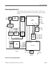
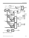
Alarm Circuitry and Fan Drive (diagram 2)
This circuitry includes the out-of-limit sensing components, the shutdown logic
circuitry, and fan speed control components. Refer to schematic diagram 2 of the
A11 power supply board for the following circuit description.
LED Indicators. LED indicators (DS2 through DS8 and DS13) are placed on the
input voltage side of the Power Supply Supervisor, U9. These indicators provide
a quick visual check to see if the expected input voltages to U9 are present if
troubleshooting of the power supply ever becomes necessary.
Power Supply Supervisor. The Power Supply Supervisor, U9, monitors the +5 V,
+15 V, and –15 V power supply voltages and the LINE SENSE input. If any of
the voltages do not meet the expected level (over or under), the Power Supply
Supervisor outputs the appropriate alarm signal (/OVERVOLTS, /PWR FAIL,
and /UNDERVOLTS). Each of the positive voltages is monitored on a separate
input. A resistive voltage divider sets the input voltage at 2.5 volts. The –15 V
supply is monitored at pin 14 of U9.
The LS input of U9, pin 5, monitors the LINE SENSE signal from the house-
keeping supply. That line also has diode-OR’ed signals from the Shutdown
Logic Gate input and the PWM regulation detector. Any of those signals going
low causes the Power Supply Supervisor to output the /PWR FAIL signal to the
main instrument to warn it that power failure is imminent.
The supervisor also develops a voltage reference from pin 3. That voltage is used
for the reference voltage in the overcurrent comparators and the power reset
comparator.
The width of the valid range (tolerance) of input voltages is set by the voltage on
pin 1 (LTH) to be 8%.
Power Reset Comparator. When the power supply is going down, it is important
that the memory devices in the AM700 are not written with random data as the
voltage decreases. There are two signals generated from the Alarm Sensing
circuitry to aid in producing an orderly shutdown of the processor and memory
devices.
These two signals are /PWR FAIL, a warning that the power supply is going
down, and /PWR RESET, a signal that prevents further writing as the voltage
continues falling to the off state. The /PWR FAIL signal is developed by the
Power Supply Supervisor, U16, immediately as the power is turned off. The
/PWR RESET signal is developed by comparator U20B as the voltage decreases
to the point that an /UNDERVOLTS signal is generated by the Power Supply
Supervisor. The time delay between the two events permits the processor to
shutdown while the voltage level is still high enough to permit proper operation.
Alarm Sensing