Table of Contents
xiv
AM700 Audio Measurement Set Service Manual
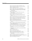
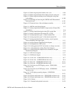
Figure 6–19: Circuit board assemblies for CRT display version 6–51. . . . . . .
Figure 6–20: Circuit board assemblies for flat panel color display 6–52. . . . .
Figure 6–21: Multiple-pin connectors 6–56. . . . . . . . . . . . . . . . . . . . . . . . . . . .
Figure 6–22: Major module locations for the CRT display 6–57. . . . . . . . . . . .
Figure 6–23: Major module locations for the LCD flat panel display 6–58. . .
Figure 6–24: Bottom view showing the connections to the Analog
Acquisition board 6–59. . . . . . . . . . . . . . . . . . . . . . . . . . . . . . . . . . . . . . . .
Figure 6–25: XLR connectors 6–61. . . . . . . . . . . . . . . . . . . . . . . . . . . . . . . . . .
Figure 6–26: Bottom view showing the XLR connector board
cable connections 6–62. . . . . . . . . . . . . . . . . . . . . . . . . . . . . . . . . . . . . . . .
Figure 6–27: Digital audio board connector locations 6–63. . . . . . . . . . . . . . .
Figure 6–28: Bottom view showing the Analog Audio Generator
cabling 6–65. . . . . . . . . . . . . . . . . . . . . . . . . . . . . . . . . . . . . . . . . . . . . . . . .
Figure 6–29: LCD Display Driver board with connector locations 6–66. . . . .
Figure 6–30: CPU board retaining screws and disk drive cable release 6–67. .
Figure 6–31: Rear panel screws holding the CPU board in place 6–68. . . . . .
Figure 6–32: Retaining screw locations for DSP (A7) circuit board 6–69. . . .
Figure 6–33: Trim ring and front panel removal 6–70. . . . . . . . . . . . . . . . . . . .
Figure 6–34: Front panel board connector locations 6–70. . . . . . . . . . . . . . . . .
Figure 6–35: Touch screen gasket precaution areas when Installing the
trim ring 6–71. . . . . . . . . . . . . . . . . . . . . . . . . . . . . . . . . . . . . . . . . . . . . . .
Figure 6–36: Disk drive flexible circuit board connector operation 6–72. . . . .
Figure 6–37: Power supply and monitor board cover plate screws and
cables (CRT display version) 6–74. . . . . . . . . . . . . . . . . . . . . . . . . . . . . . .
Figure 6–38: Trim ring and LCD flat panel display retaining screws 6–77. . . .
Figure 6–39: Touch screen assembly removal B020253 to B020692 6–79. . . .
Figure 6–40: Touch screen removal for serial number B020633
and above 6–80. . . . . . . . . . . . . . . . . . . . . . . . . . . . . . . . . . . . . . . . . . . . . .
Figure 6–41: LCD assembly exploded view serial number B020100
to B020632 6–81. . . . . . . . . . . . . . . . . . . . . . . . . . . . . . . . . . . . . . . . . . . . .
Figure 6–42: Backlight removal 6–84. . . . . . . . . . . . . . . . . . . . . . . . . . . . . . . .
Figure 6–43: Touch panel reinstallation 6–86. . . . . . . . . . . . . . . . . . . . . . . . . .
Figure 6–44: Power supply connector locations 6–87. . . . . . . . . . . . . . . . . . . .
Figure 6–45: Location of the backup battery in the AM700 6–89. . . . . . . . . . .
Figure 6–46: Partial CPU board showing location of BT1, the
backup battery 6–89. . . . . . . . . . . . . . . . . . . . . . . . . . . . . . . . . . . . . . . . . . .
Figure 6–47: Exploded view of the slide-out track assembly 6–94. . . . . . . . . .
Figure 6–48: Locating mounting holes on front Rrails of equipment rack 6–95
Figure 6–49: Mounting the slide to the front rail 6–96. . . . . . . . . . . . . . . . . . .
Figure 6–50: Installing bracket extensions 6–96. . . . . . . . . . . . . . . . . . . . . . . .


