


Diagnostics
6–36
AM700 Audio Measurement Set Service Manual
4. Read boot diagnostic status from the DRAM.
a. Encode the 8-bit boot step number into the USP LSByte.
b. Write “4” on the diagnostic LED display.
c. Read the boot diagnostics status from DRAM.
Since a location that may not yet have been written is being read, we
could get a parity induced access error (exception 2) here if the Board
Program Register fails to mask parity exceptions. There may also be a
bus error induced access error on the read. It will be necessary to
physically probe the hardware to determine the actual cause.
5. Test the DRAM data bus.
a. Encode the 8-bit boot step number into the USP LSByte.
b. Write “5” on the diagnostic LED display.
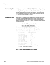
c. For each of the 32 data lines, 0–31:
Write a test pattern with just that line HIGH to 0x30000100:
0x00000001, 00000002, 00000004, 00000008, 00000010,
0x00000020, 00000040, 00000080, 00000100, 00000200,
0x00000400, 00000800, 00001000, 00002000, 00004000,
0x00008000, 00010000, 00020000, 00040000, 00080000,
0x00100000, 00200000, 00400000, 00800000, 01000000,
0x02000000, 04000000, 08000000, 10000000, 20000000,
0x40000000, 80000000
Write the inverse pattern to the diagnostic LED register, to precharge the
data bus with the opposite of what expect to read back.
Verify that we read back the test pattern from 0x30000100.
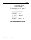
d. If that pattern test passes, do the test again using a pattern with just the
data line under test LOW:
0xfffffffe, fffffffd, fffffffb, fffffff7, ffffffef,
0xffffffdf, ffffffbf, ffffff7f, fffffeff, fffffdff,
0xfffffbff, fffff7ff, ffffefff, ffffdfff, ffffbfff,
0xffff7fff, fffeffff, fffdffff, fffbffff, fff7ffff,
0xffefffff, ffdfffff, ffbfffff, ff7fffff, feffffff,
0xfdffffff, fbffffff, f7ffffff, efffffff, dfffffff,
0xbfffffff, 7fffffff
e. If either test fails, indicate the bad line (d0–d31) by showing a “d” and
then the hex char “0”–”.F” (0–31) on the diagnostic LED display.